Light guides and backlight systems incorporating prismatic structures and light redirectors

a technology of prismatic structure and light redirector, applied in the field of displays, to achieve the effect of increasing the efficiency of light distribution

Active Publication Date: 2009-10-15
SNAPTRACK
View PDF99 Cites 45 Cited by
  • Summary
  • Abstract
  • Description
  • Claims
  • Application Information

AI Technical Summary

Benefits of technology

[0010]In another aspect, the invention relates to the placement and orientation of transparent prismatic structures placed between the light guide and the modulator plate. In one embodiment, the placement of these transparent prismatic structures is both in rear-facing (towards the light guide) and front-facing (towards the modulator) orientations. The combination of diverge/converge action of the structures on the cone angle of the light passing through the structures increases the efficiency of the light distribution. In another embodiment, these prismat

Problems solved by technology

Such illumination schemes increase the challenge of provi

Method used


Image

  • Light guides and backlight systems incorporating prismatic structures and light redirectors
  • Light guides and backlight systems incorporating prismatic structures and light redirectors
  • Light guides and backlight systems incorporating prismatic structures and light redirectors

Examples


Embodiment Construction

[0029]To provide an overall understanding of the invention, certain illustrative embodiments will now be described, including backlights and backlight systems for providing illumination for a display. However, it will be understood by one of ordinary skill in the art that the backlights and backlight systems described herein may be adapted and modified as is appropriate for the application being addressed and that the systems and methods described herein may be employed in other suitable applications, and that such other additions and modifications will not depart from the scope hereof.

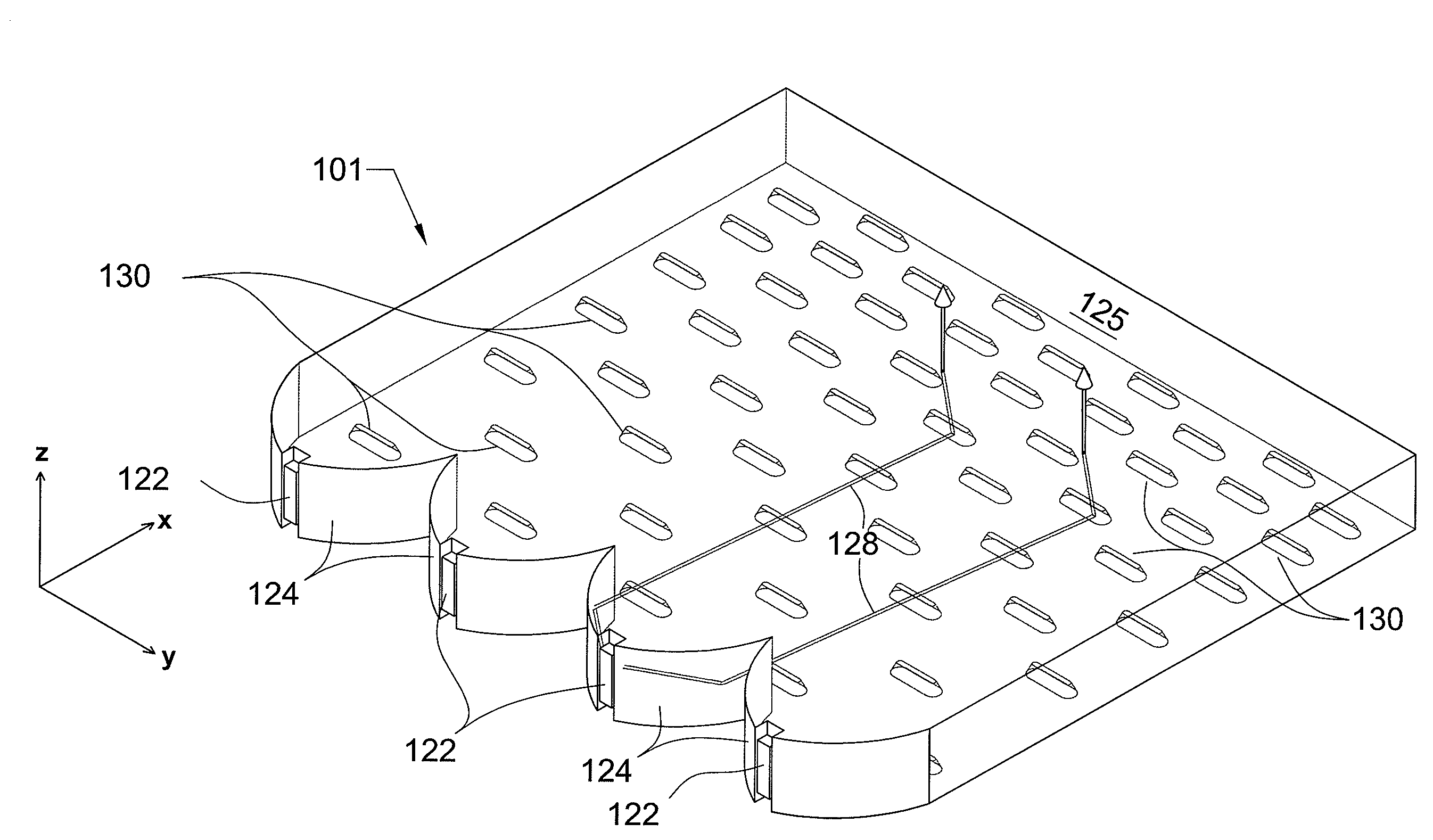
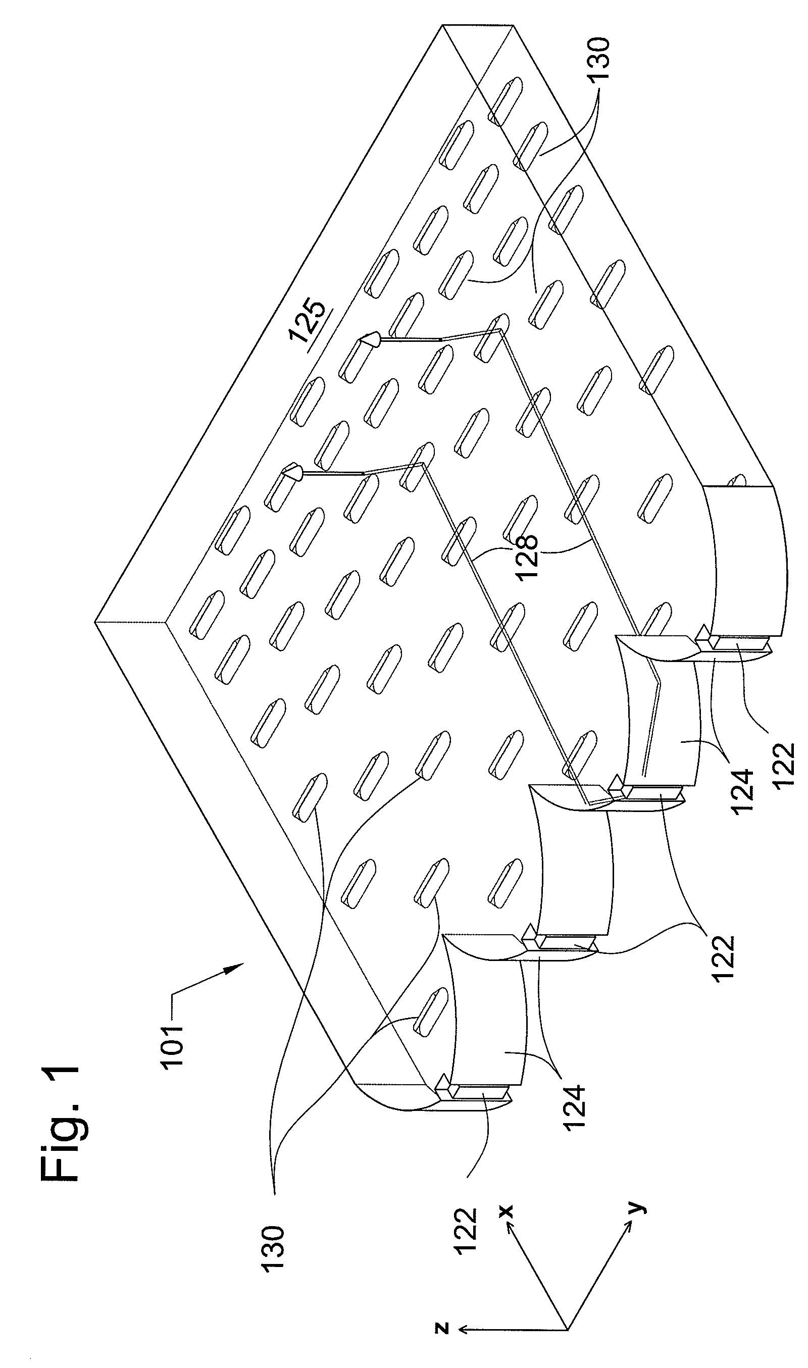
[0030]FIG. 1 illustrates a backlight system 101 that is useful in conjunction with a number of optical illumination devices, including liquid crystal displays (LCD) or mechanical light modulator displays, including shutter-based, roller actuator, and electrowetting light modulating devices. The backlight system 101 includes a light guide plate 125, made of a transparent material that accepts light fro...


PUM


Abstract

Improved apparatus and method for collecting and directing light from a source via a light guide and modulated display assembly in an efficient manner through the design and use of prismatic optical structures, diffusers and/or light redirectors.

Description

CROSS REFERENCE TO RELATED APPLICATIONS[0001]This application claims priority to U.S. Provisional Patent Application No. 61 / 124,168, entitled “Display Apparatus with Improved Optical Cavities,” and filed on Apr. 14, 2008, the entirety of which is incorporated herein by reference.FIELD OF THE INVENTION[0002]The present invention generally relates to the field of displays, such as imaging and projection displays. In particular, the invention relates to the coordinated design and use of prismatic optical structures, diffusers and / or light redirectors in maximizing the utilization of light in such devices.BACKGROUND OF THE INVENTION[0003]The displays of many portable devices rely on backlights to provide their illumination. Viewers of these displays desire uniform light emission across the surface of a display with as few visual artifacts as possible. As screens become larger, multiple spatially separated light sources are used to illuminate the backlight. Such illumination schemes incr...

Claims


Application Information

Patent Timeline
IPC IPC(8): F21V7/04
CPCG02B6/0036G02B6/0038F21V7/04G02B6/0061G02B6/0053
Inventor KIM, JE HONGGANDHI, JIGNESH
Owner SNAPTRACK
Why Eureka
Try Eureka