Thermal protection of electro dynamic transducers used in loudspeaker systems

Active Publication Date: 2009-10-15
BANG & OLUFSEN ICEPOWER
View PDF3 Cites 61 Cited by
  • Summary
  • Abstract
  • Description
  • Claims
  • Application Information

AI Technical Summary

Benefits of technology

[0024]c) An optional procedure, where the estimated resistance from step

Problems solved by technology

It has been known since the 1970's that overheating of the voice coil of electro dynamic transducers is one of the main causes of failure of such transducers.
However, music is very dynamic, which means that such a static limit is far from optimal, because the transducers can handle much more power than the maximum power rating for shorter periods of time.
With such a system it would not be possible to damage the transducer even though more power than the maximum rated power is applied for shorter periods of time.
However, as of today such protection systems have not seen widespread commercial use.
1) Feed forward protection systems, where the voice coil temperature is predicted using a thermal transducer model. The signal is then attenuated based on the predicted temperature. Such systems are very susceptible to modeling inaccuracies, as well as the fact that the ambient temperature is a very important parameter for the temperature prediction model. This means that either a given ambient temperature is assumed, which can be inaccurate, or an ambient temperature sensor is required, which increases the complexity and adds cost.
2) Feedback systems, where the temperature is measured in one way or another. Typically, since the voice coil is moving, it is difficult to attach a temperature sensor directly to the voice coil. Therefore, in such systems, the tempera

Method used


Image

  • Thermal protection of electro dynamic transducers used in loudspeaker systems
  • Thermal protection of electro dynamic transducers used in loudspeaker systems
  • Thermal protection of electro dynamic transducers used in loudspeaker systems

Examples


Embodiment Construction

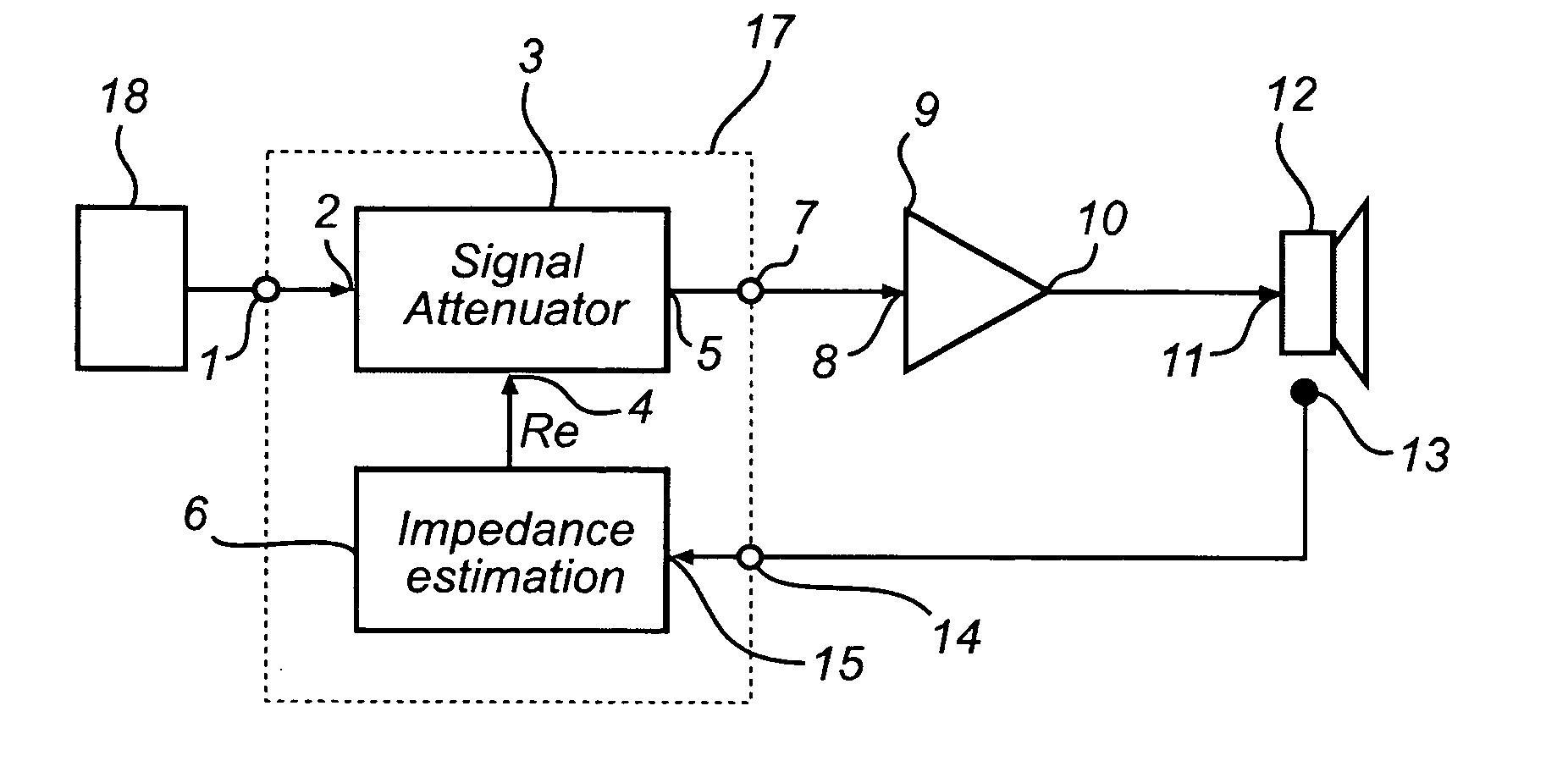
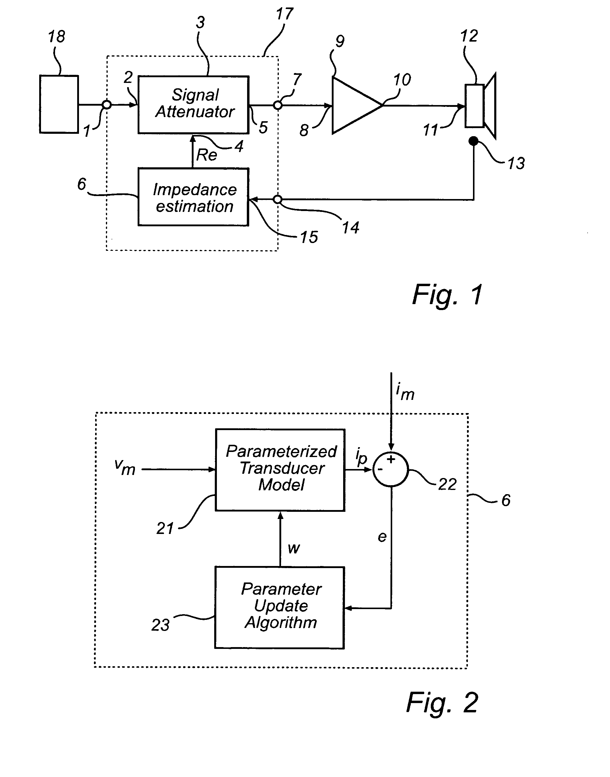
[0029]FIG. 1 shows a thermal protection system 17 intended to be used together with an audio power amplifier 9, and an electro dynamic transducer 12. The protection system 17 comprises an impedance estimator 6, and an attenuator 3. The thermal protection system may be implemented as a digital controller, e.g. a micro processor or a digital signal processor, arranged to execute a thermal protection algorithm to be described below.

[0030]In a preferred embodiment the input 1 of the thermal protection system 17 is connected to a digital audio signal source 18. The input 1 is then connected to the signal attenuator 3, performing an attenuation function based on an estimated value of the electrical resistance (Re) of the electro dynamic transducer 12, determined by the estimator 6.

[0031]The output 5 of the signal attenuator 3 is connected through the output 7 of the protection system 17 to the input 8 of an audio power amplifier 9. The output 10 of the audio power amplifier is connected t...


PUM


Abstract

Electro dynamic transducers can fail due to either excessive voice coil excursion, causing mechanical clipping, or by overheating of the voice coil causing degradation of the materials. The disclosed invention relates to protection against excess voice coil temperature in such transducers. The current through the transducer voice coil and the voltage across its terminals, are measured. The resistive part of the impedance of the transducer is then estimated based on the measurements of current and voltage. When the resistive impedance for the given type of transducer is well known at one temperature it is then possible to calculate the temperature when the resistive impedance changes. The estimated voice coil temperature is then fed to a signal attenuator or controller, which attenuates the output signal to the transducer.

Description

PRIORITY STATEMENT[0001]This application claims the benefit of Danish Patent Application No. 2008 00527, filed on Apr. 10, 2008, in the Danish Patent and Trademark Office, the disclosure of which is incorporated herein in its entirety by reference.TECHNICAL FIELD OF THE INVENTION[0002]The present invention relates to protection against excess voice coil temperature in loudspeaker transducers.[0003]In standard loudspeaker systems electro dynamic transducers can fail due to overheating of the voice coil causing degradation of the materials. The present invention relates to improvements in that respect.BACKGROUND OF THE INVENTION[0004]It has been known since the 1970's that overheating of the voice coil of electro dynamic transducers is one of the main causes of failure of such transducers. Therefore, transducer manufacturers normally specify a maximum power rating, which they can guarantee that the transducer will survive being exposed to for an extended period of time. However, music...

Claims


Application Information

Patent Timeline
IPC IPC(8): H03G11/00
CPCH03F1/52H03F2200/03H04R9/022H03G3/301H03F2200/426
Inventor SAND JENSEN, BJORNSOLGAARD, MADS EMIL
Owner BANG & OLUFSEN ICEPOWER
Why Eureka
Try Eureka