Broadband tuner for very wide signal conversion

a wide signal and tuner technology, applied in the field of radio frequency (rf) tuners, can solve the problems of user's inability to specify the carrier a user wishes, and achieve the effect of not impairing the performance of the desired signal, reducing the disadvantages and problems of prior rf tuners, and low energy level and/or order

Inactive Publication Date: 2009-10-15
CSR TECH INC
View PDF10 Cites 23 Cited by
  • Summary
  • Abstract
  • Description
  • Claims
  • Application Information

AI Technical Summary

Benefits of technology

[0005]In accordance with embodiments of the present invention, disadvantages and problems associated with prior RF tuners have been substantially reduced or eliminated. According to particular embodiments, an agile RF tuner has a frequency conversion architecture that converts wide portions (e.g., ten percent or more) of a received RF broadband spectrum to an IF output signal. According to certain embodiments, the IF signal is utilized in a number of applications, including television and mobile phone reception. For example, embodiments used in television reception applications can be tuned to receive between 50 MHz and 1.1 GHz of RF spectrum and convert approximately 100 MHz or more of that spectrum to an IF signal. To that end, a preferred embodiment utilizes a bandpass filter implemented as a switched filter having an analog trim and a plurality of filters configured to provide a minimum number of spurious product bands in the desired IF signal. Embodiments thus provide a desired IF signal that is substantially free of spurious emission (i.e., spurious emissions are sufficiently low in energy level and / or order so as not to impair the performance of the desired signal). Slope adjustment circuitry maintains flat spectral power of the IF signal thereby improving tuner utility. A lowpass and bandpass filter output are supported by the tuner, this allows further supression of harmonics and improves tuner output.
[0008]Other embodiments provide a front end for applications such as software-defined radio and the like. These embodiments allow broadband digital systems to examine broad portions of received spectrum and determine what portions of that spectrum need to be demodulated. Additional embodiments provide frequency agile movement between signals where one band of signals can be converted up or down to another band of signals. These features are particularly useful in, for example, on-channel processor or signal processor applications.

Problems solved by technology

In practice, cable providers often change the transmission frequency of its programming; as such, there is no guarantee as to where the carriers a user wishes to receive will be located.

Method used


Image

  • Broadband tuner for very wide signal conversion
  • Broadband tuner for very wide signal conversion
  • Broadband tuner for very wide signal conversion

Examples


Embodiment Construction

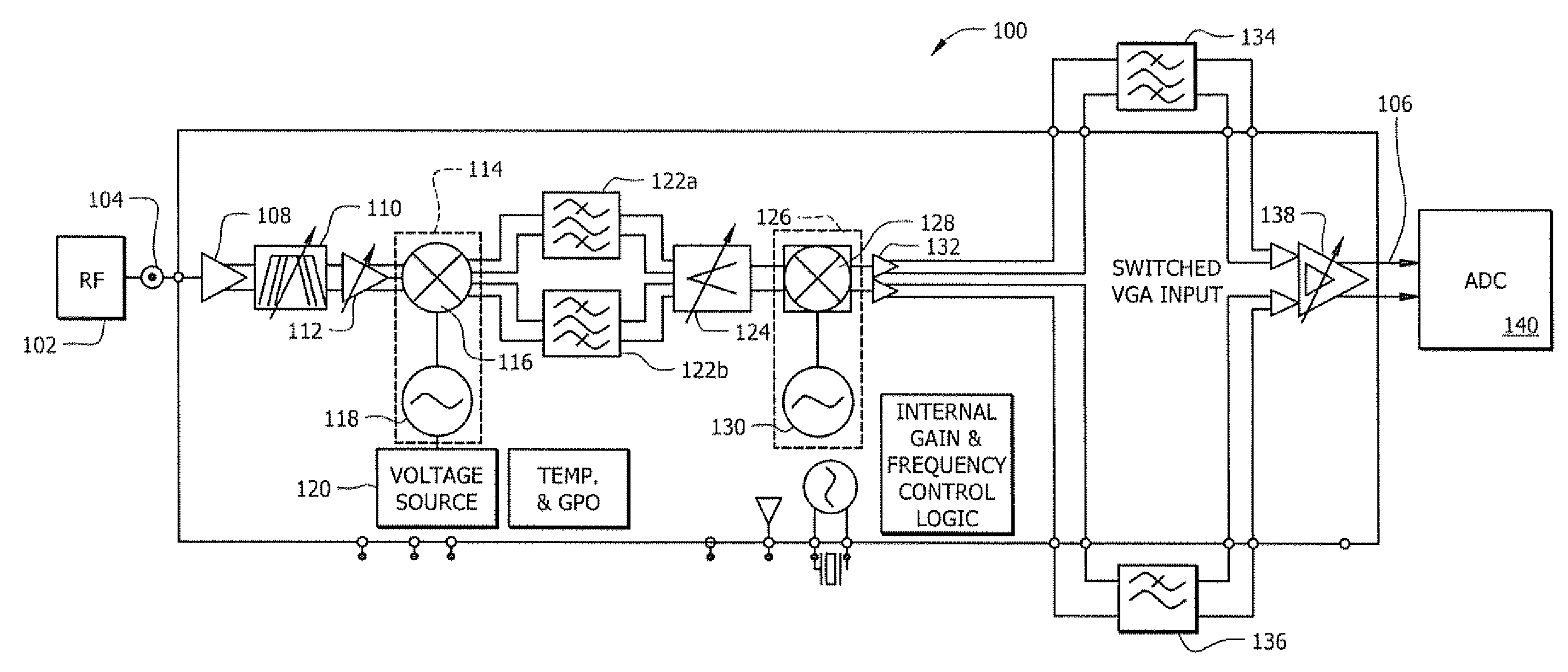
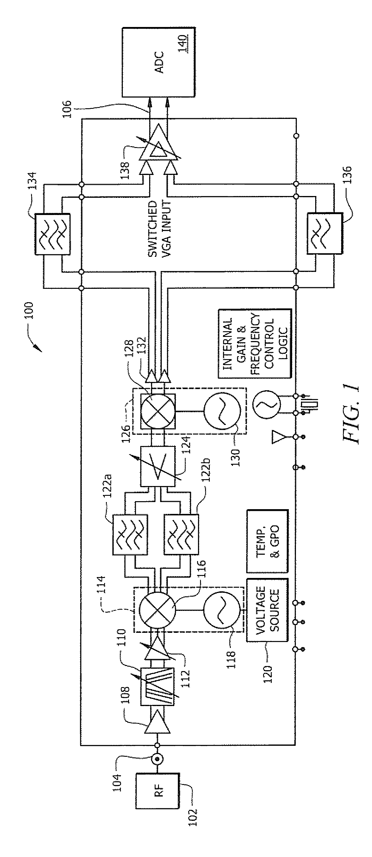
[0014]FIG. 1 illustrates an exemplary embodiment of a tuner circuit 100 for frequency agile conversion of a relatively wide frequency range of a Radio Frequency (RF) broadband signal into an Intermediate Frequency (IF) signal. The architecture of circuit 100 provides for an RF tuner that is both agile and able to convert a relatively wide portion (e.g. 10 percent or more) of an incoming RF broadband signal into an IF signal. Moreover, the circuitry of the preferred embodiment is configured to utilize integrated components such that a synergistic cascade of component attributes provides an output signal having a desired signal quality, such as a signal quality meeting video transmission head end requirements. Embodiments of tuner circuit 100 can be implemented in a number of RF tuner applications, not the least of which includes digital television and high speed data reception.

[0015]According to the embodiment shown in FIG. 1 RF signal 102 enters circuit 100 at input 104. RF tuner si...


PUM


Abstract

An agile RF tuner circuit capable of converting a wide portion of RF signal into an IF signal suitable for analog-to-digital conversion. The circuit up converts a received RF signal to a high IF signal and then down converts the high IF signal to a low IF signal. Embodiments of the RF circuit incorporate harmonic reject mixers to suppress harmonies and intermodulations typically associated with the frequency conversion process.

Description

TECHNICAL FIELD[0001]The present invention generally relates to Radio Frequency (RF) tuners. More specifically, the present invention relates to an agile RF tuner that converts a relatively wide portion of an incoming RF signal from a broadband signal to an Intermediate Frequency (IF) signal.BACKGROUND OF THE INVENTION[0002]RF tuners are involved in several different communications applications including mobile phone communications and analog and digital TV reception. Tuners are often used to convert a portion of a received RF broadband signal into an IF output signal, which, for example, may later be digitized or processed to baseband. Generally, RF tuners are considered to be either “fixed frequency” or “agile.” Conventional fixed frequency tuners are generally able to utilize a relatively wide bandwidth portion of an incoming RF signal. For instance, known fixed frequency tuners are capable of utilizing approximately one percent of a received RF broadband signal. However, fixed f...

Claims


Application Information

Patent Timeline
Patent Type & Authority Applications(United States)
IPC IPC(8): H04B1/26
CPCH04B1/28H03D7/161H04B1/0035
Inventor RITCHEY, CAREYBEUMER, KIM E.POP, MARIUS
Owner CSR TECH INC
Why Eureka
Try Eureka