Method of manufacturing coil assembly unit for rotary electric machine

Active Publication Date: 2009-10-22
DENSO CORP
View PDF9 Cites 9 Cited by
  • Summary
  • Abstract
  • Description
  • Claims
  • Application Information

AI Technical Summary

Benefits of technology

[0014]In this way, forming the bent portions allows the turn portions of a pair of formed coil wires to be woven with no spatial interference therebetween. In particular, when a large number of formed coil wires are subjected to the coil weaving step (for example, one coil wire is woven with five woven coil wires, two woven coil wires are woven with other two woven coil wires, or four woven coil wires are woven with other four woven coil wires), the width between mutually liner portions become narrower. Even in such a state, the bent portions are reliably avoided from being interfered with each other during the coil weaving step. This makes it possi

Problems solved by technology

This will thus lead to a problem that the coil wires are likely to deform.
If the coil wires are deformed when being woven, the woven coils are also resulted in having distorted shapes, whereby it is difficult to provide coil assembly units with precision.
In addition, the foregoing conceivable

Method used


Image

  • Method of manufacturing coil assembly unit for rotary electric machine
  • Method of manufacturing coil assembly unit for rotary electric machine
  • Method of manufacturing coil assembly unit for rotary electric machine

Examples


Embodiment Construction

[0035]With reference to the accompanying drawings, embodiments of the present invention will now be described, in which how to manufacture a coil assembly for a rotary electric machine, according to the present invention, will now be described.

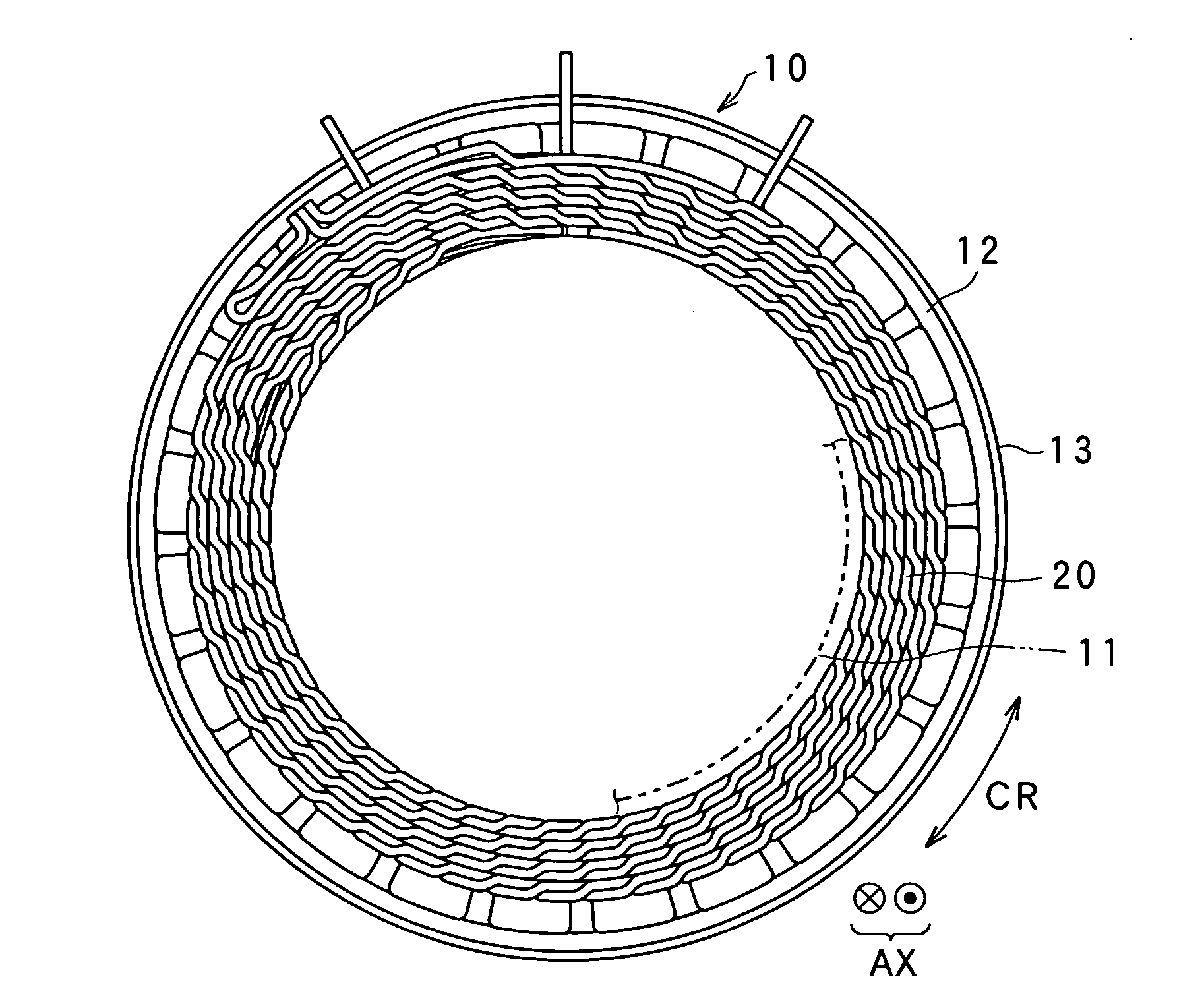
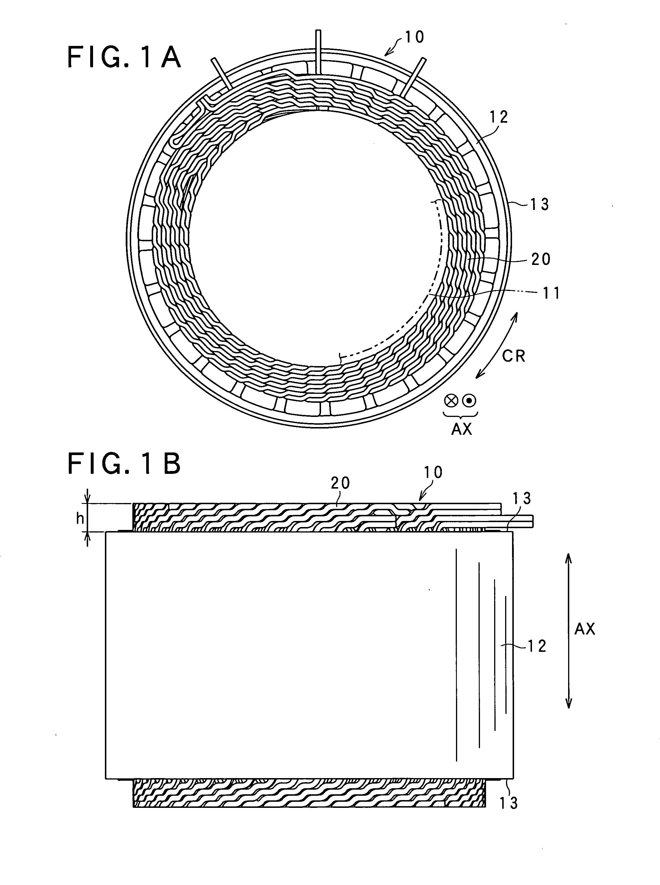
[0036]FIGS. 1A and 1B outline a rotor 10 for the rotary electric machine which is for example an alternator, a motor, or a motor generator for a vehicle. FIG. 1A shows a perspective view of the rotor 10, while FIG. 1B shows a side view of the rotor 10. This rotor 10 is manufactured with a coil assembly 20, which can be assembled based on various manufacturing methods provided various embodiments of the present invention.

[0037]The stator 10 shown in FIGS. 1A and 1B is used by, for example, a rotary electric machine called a motor generator for a vehicle, which works as an electric motor as well as a generator. The stator 10 has a bore in which a stator 11 is accommodated. Though not detailed, the rotor 11 has a plurality of magnetic poles of wh...


PUM

PropertyMeasurementUnit
Angleaaaaaaaaaa
Widthaaaaaaaaaa

Abstract

A method of manufacturing a coil assembly unit comprises steps of coil forming, weaving, compressing steps. In the forming step, each coil wire is formed which provides linear portions and turn potions each connecting linear portions, during which bent portions are formed at both ends of each linear portion, the bent portions being bent so that mutually adjacent linear portions are deviated from each other. In the weaving step, the coil wires are mutually woven in turn, in which the turn portions intersect in turn. All the coil wires are subjected to the weaving step in turn to produce a woven coil assembly. In the compressing step, the woven coil assembly is compressed by compressing the woven coil so that each bent portion is deformed to be linear to allow the mutually adjacent linear portions to come closer to each other, thus producing the coil assembly unit.

Description

CROSS-REFERENCE TO RELATED APPLICATION[0001]This application is based on and claims the benefit of priority from earlierJapanese Patent Application No. 2008-110777 filed Apr. 21, 2008, the description of which is incorporated herein by reference.BACKGROUND OF THE INVENTION[0002]1. Technical Field of the Invention[0003]The present invention relates to a method of manufacturing a coil assembly unit for a rotary electric machine.[0004]2. Related Art[0005]In general, rotary electric machines, such as motors, generators, and motor generators, need coil assembly units in which coil wires are assembled together to induce current therethrough or generate a magnetic field by supplying current therethrough. To manufacture such coil assembly units, there have been known various manufacturing methods.[0006]For example, Japanese Patent Laid-open Publication No. 2002-176752 discloses one manufacturing method, in which a pair of plate-like winding cores, which are located to be opposed to each oth...

Claims


Application Information

Patent Timeline
IPC IPC(8): H01F7/06
CPCH02K15/0478Y10T29/4902Y10T29/49066Y10T29/49073Y10T29/49071
Inventor AKIMOTO, AKITO
Owner DENSO CORP
Why Eureka
Try Eureka