Compressed-Air Rigid Building Blocks

a technology of rigid building blocks and compressed air, applied in the direction of machines/engines, instruments, printing, etc., to achieve the effect of high modulus, high strength and high strength

Inactive Publication Date: 2009-10-22
PRUEITT MELVIN L
View PDF13 Cites 10 Cited by
  • Summary
  • Abstract
  • Description
  • Claims
  • Application Information

AI Technical Summary

Benefits of technology

[0020]It is therefore an object of the present invention to provide a rigid box-like structure that is caused to retain its shape by internal air pressure (or other gas pressure) and by high strength, high modulus filaments that are attached to opposite faces of the structure.
[0021]It is another object of the present invention provide a rigid cylindrical structure that is caused to retain its shape by internal air pressure (or other gas pressure) and by high strength, high modulus filaments that are attached to the top

Problems solved by technology

High air pressure in an air bag can support heav

Method used


Image

  • Compressed-Air Rigid Building Blocks
  • Compressed-Air Rigid Building Blocks
  • Compressed-Air Rigid Building Blocks

Examples


Embodiment Construction

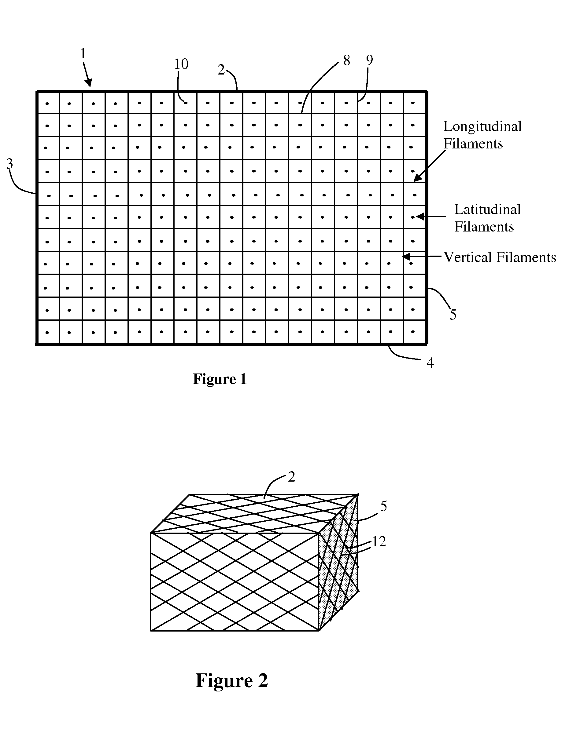
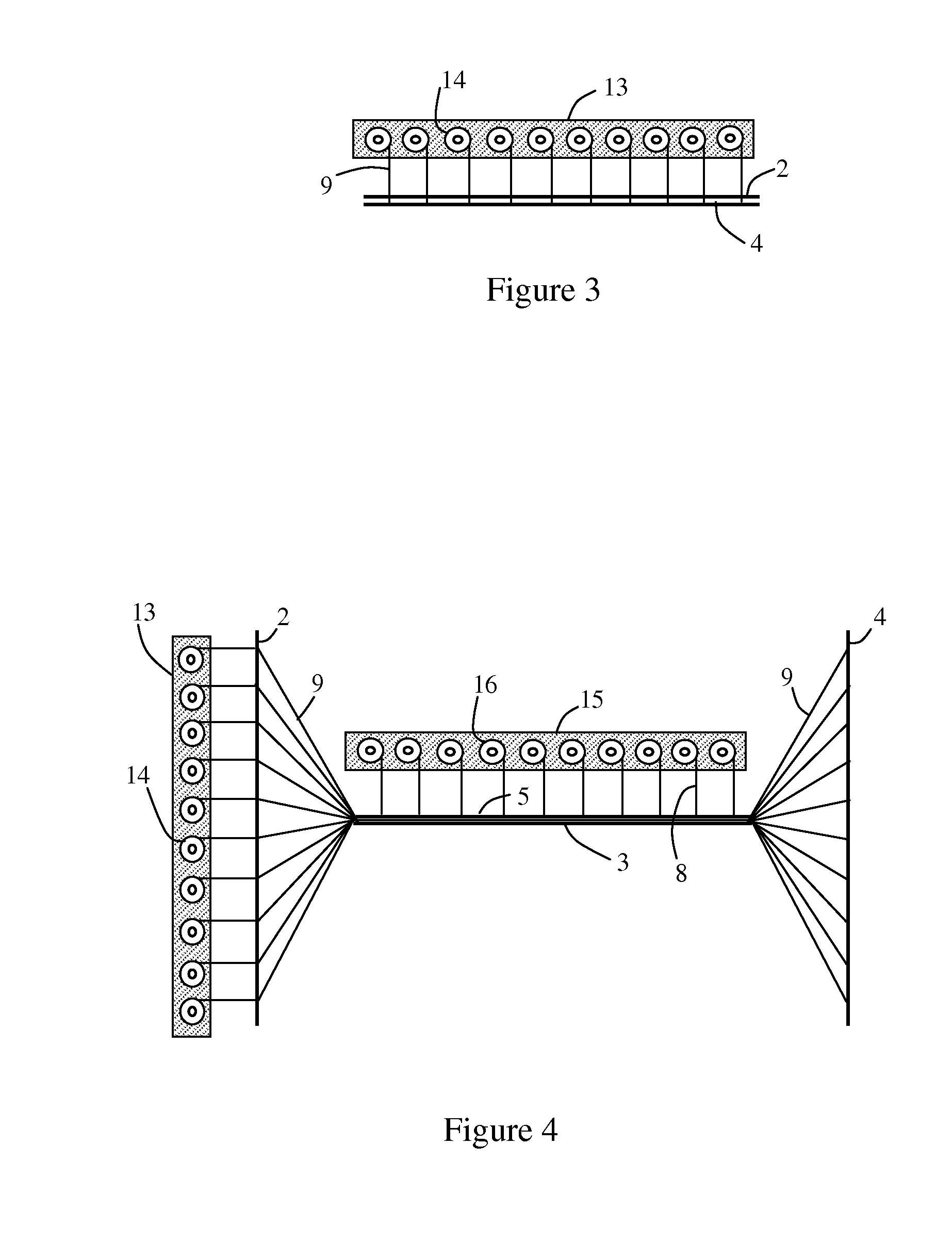
[0041]FIG. 1 shows one design of a CARBB 1 in cross sectional side view. The faces 2, 3, 4 and 5 of the CARBB can be made of thin, tough composite plastic material or other airtight material. The top face 2 and bottom face 4 can be somewhat rigid. Side faces 3 and 5, as well as the front and back faces (not shown) should be flexible so that the box can be folded down for shipping. Horizontal filaments 8 and vertical filaments 9 are shown. The dots 10 represent filaments that run in the third dimension (perpendicular to the page). The filaments hold the faces in place against the inside air pressure. In this design, the filaments 9 and 10 run through the side faces and are attached to rectangular plastic or metal washers, which distribute the force from the filaments to the face material. Filaments 8 pass through the top and bottom faces and are attached to the outside of those faces. On the side faces 3 and 5 (as well as the front and back faces), there should be small gaps between ...


PUM


Abstract

The outstanding tensile strength of some materials are used in compression applications by using air pressure to supply the outward force on an enclosure and by using interior tension members to maintain the geometry of the air-pressurized structure. The air pressure on each face of the structure is balanced by the tension in the tension members. Due to the high modulus of the tension members, the air-pressurized structures are very rigid. It is the air pressure that actually supports any load placed on the structure, but it is the tension members that maintain the geometry when the load is removed, and the strength of the tension members determine how much air pressure can be sustained. The mass of tension material required in such a structure is roughly equivalent to the amount of filament material required in a cable to support the same load. The Compressed-air Rigid Building Blocks can be stacked like bricks to form strong, lightweight walls, buildings, towers, and other structures.

Description

CROSS-REFERENCE TO RELATED APPLICATION[0001]This claims priority to and the benefit of U.S. Patent Provisional Application No. 61 / 046,878, filed Apr. 22, 2008, the entirety of which is incorporated herein by reference.BACKGROUND OF THE INVENTION[0002]For load-bearing structures, we normally need materials with high compressive strength. However, in order to use these materials effectively, large masses are required. A filament, a wire, or a cable of the material would be useless in the compressive mode. There are materials that have very high tensile strengths that can support large loads as a cable, if the support is supplied from above the load. Unfortunately in practice, most loads are supported from below. I propose herein a method for using the high tensile strengths of some materials to support loads in the compressive mode. This means that building blocks could be much lighter than the standard load-bearing materials such as masonry bricks, concrete, or steel beams. (Since “w...

Claims


Application Information

Patent Timeline
IPC IPC(8): E04H15/20D05B87/00B65H57/26
CPCE04H15/20E04H2015/205Y02E10/72F05B2240/131Y02B10/30F03D1/04Y02E10/728F03D9/37F03D9/25
Inventor PRUEITT, MELVIN L.
Owner PRUEITT MELVIN L
Why Eureka
Try Eureka