Solar thermal power plant

a technology of solar energy and power plant, applied in the direction of machines/engines, lighting and heating apparatus, transportation and packaging, etc., can solve the problem of costly reheating of working fluid

Inactive Publication Date: 2009-10-22
ALSTOM TECH LTD
View PDF15 Cites 70 Cited by
  • Summary
  • Abstract
  • Description
  • Claims
  • Application Information

AI Technical Summary

Problems solved by technology

This preheating of the working fluid is costly, requiring addi

Method used


Image

  • Solar thermal power plant
  • Solar thermal power plant
  • Solar thermal power plant

Examples


Embodiment Construction

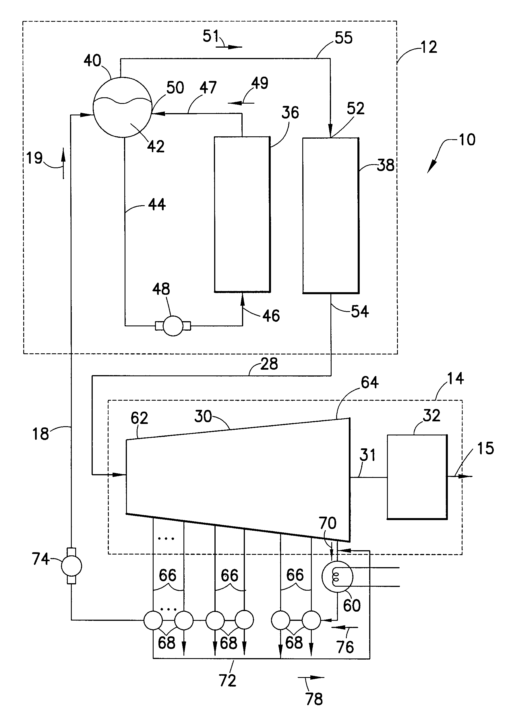
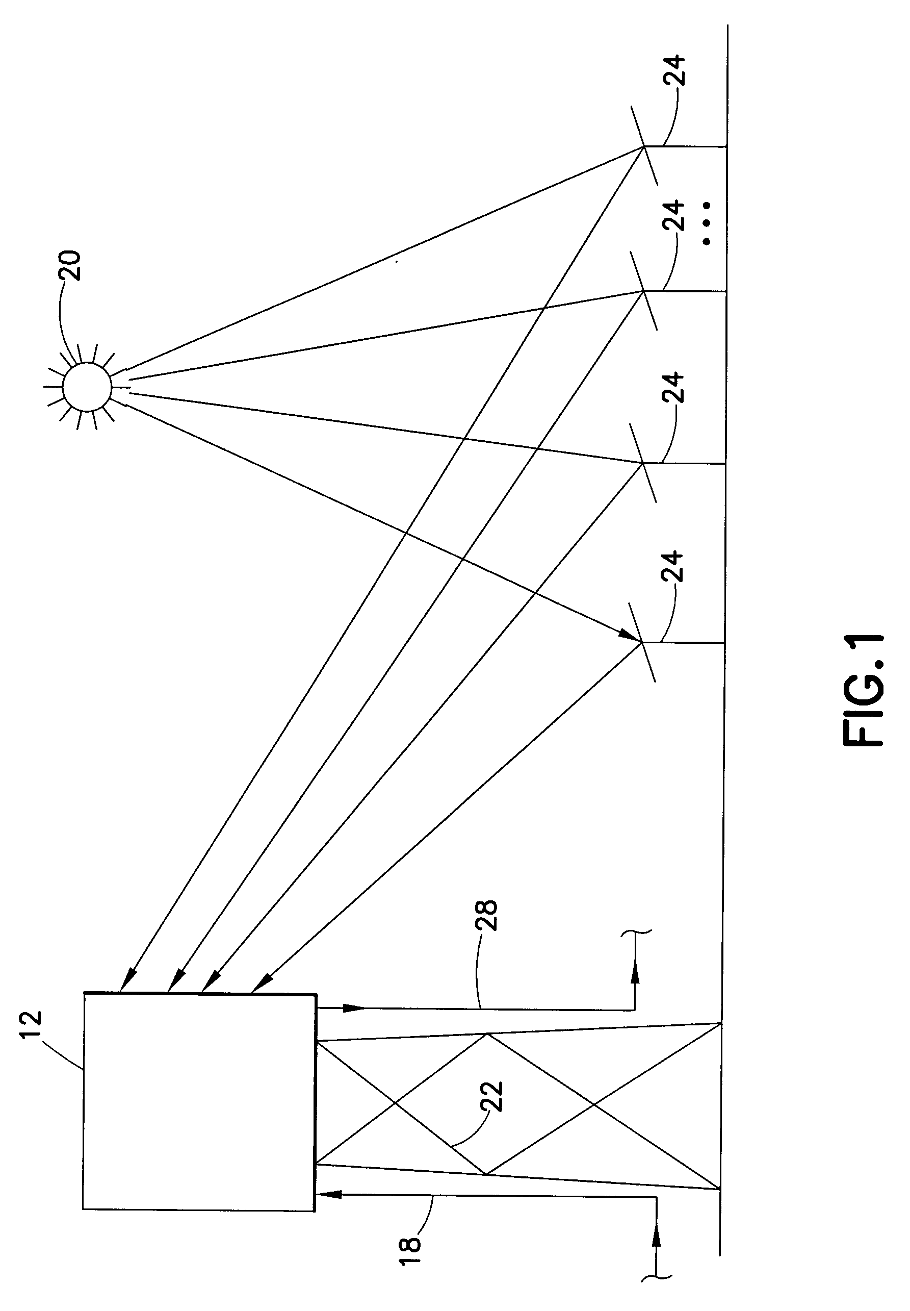
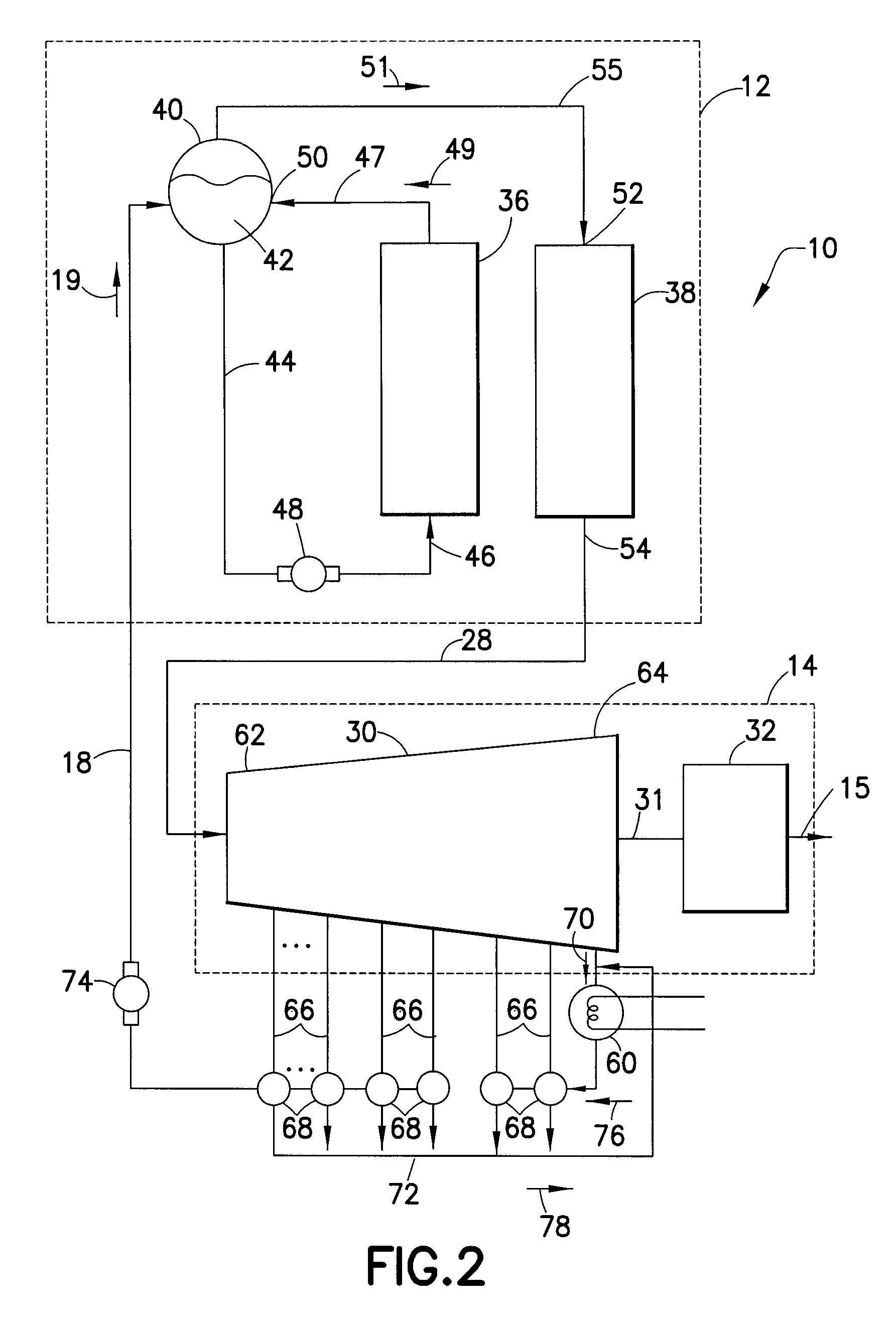
[0012]In one embodiment of the invention, a solar steam power generation system or solar thermal power plant 10 is shown in FIGS. 1 and 2, whereby water is heated in a steam generation portion or a solar receiver 12 to produce steam for rotating a steam turbine generator 14, which generates electricity 15. The solar receiver 12 comprises at least one panel of tubes (or tubing) 36, 38 that receives water (or other fluid) from an input pipe or conduit 18. As will be described in greater detail hereinafter, the solar receiver 12 may include a plurality of panels that perform different functions for transferring the radiant heat of the sun 20 to the water and / or steam flowing through the panel of tubes 36, 38.

[0013]As shown in FIG. 1, the solar receiver 12 may be disposed on a tower 22 among a field of solar collectors 24, such as mirrors or heliostats. The solar collectors 24 are arranged proximate the tower for directing solar energy or solar radiation from the sun 20 to the solar rec...


PUM


Abstract

A solar thermal power plant 10 includes a steam generation portion 12 and a turbine 30. The steam generation portion 12 includes a steam drum 50 that separates water and steam, and an evaporator 36 and super heater 38 in fluid communication with the steam drum. The evaporator 36 receives and heats a portion of a flow of water from the steam drum 50 to provide the steam using solar energy provided thereto. The super heater 38 heats the steam from the evaporator 36 to provide super heated steam. A turbine 30 receives the super heated steam from the steam generation portion 12 to rotate the turbine. A plurality of extraction stages 66 extracts steam from the turbine 30 and provides the steam to a plurality of feedwater heaters 68. The feedwater heaters 68 heat the feedwater provided by the turbine 30, wherein the heated feedwater is provided to the steam generation portion 12.

Description

CROSS REFERENCE TO RELATED APPLICATIONS[0001]This application claims the benefit under 35 U.S.C. § 119(e) of co-pending U.S. Provisional Application Ser. No. 61 / 057,360, filed on May 30, 2008, and co-pending, U.S. Provisional Application Ser. No. 61 / 045,361, filed on Apr. 16, 2008, the contents of both applications being incorporated by reference herein in their entireties.TECHNICAL FIELD[0002]The present disclosure relates generally to a solar thermal power plant, and more particularly, to a solar thermal power plant having a plurality of preheaters utilizing steam extracted from a steam turbine to improve steam generation efficiency within the power plant.BACKGROUND[0003]In conventional power plants, fossil fuels are typically burned to generate steam, which is used to drive power-generating devices. In such plants, water is fed to a boiler using the fossil fuels to heat the water and generate steam. The steam is then used to drive turbine generators that generate electricity. In ...

Claims


Application Information

Patent Timeline
IPC IPC(8): F03G6/00
CPCF01K3/06F01K3/262F01K7/40Y02E10/46F03G6/065F24J2/07F24J2/16F01K17/00F24S20/20F24S23/77
Inventor PALKES, MARK
Owner ALSTOM TECH LTD
Why Eureka
Try Eureka