Inflatable solar energy collector apparatus

Active Publication Date: 2009-10-22
FLORIDA STATE UNIV RES FOUND INC
View PDF15 Cites 46 Cited by
  • Summary
  • Abstract
  • Description
  • Claims
  • Application Information

AI Technical Summary

Benefits of technology

[0011]The collector is preferably adjustable in azimuth to accurately track the sun's motion across the sky. It is able to operate efficiently without the need for altitude adjustment, although altitude adjustment may also be optionally provided. The invention preferably incorporates a novel energy receiver in which stagnant air is entrapped and used as an insulator. The invention may also feat

Problems solved by technology

These solutions typically involve expensive coated glass surfaces.

Method used


Image

  • Inflatable solar energy collector apparatus
  • Inflatable solar energy collector apparatus
  • Inflatable solar energy collector apparatus

Examples


Embodiment Construction

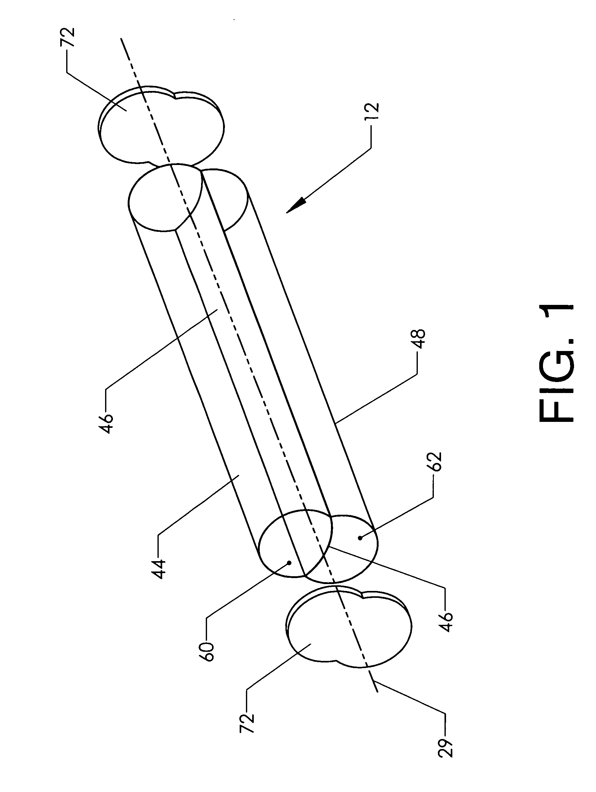
[0035]FIG. 1 shows the major components of the present invention in an exploded view. Inflatable trough reflector 12 is preferably a long and slender assembly aligned with central axis 29. It may be much longer than the version illustrated. The invention is preferably made by joining thin and flexible films together. The embodiment of FIG. 1 has three such films—clear layer 44, middle reflective layer 46, and back layer 48.

[0036]The films are typically made of plastic. Clear layer 44 should be optically transparent. Middle reflective layer 46 is coated with a reflective substance on the side facing upward in the view. Back layer 48 may be opaque, though as it is convenient to use the same material for the clear layer and the back layer it may be clear as well.

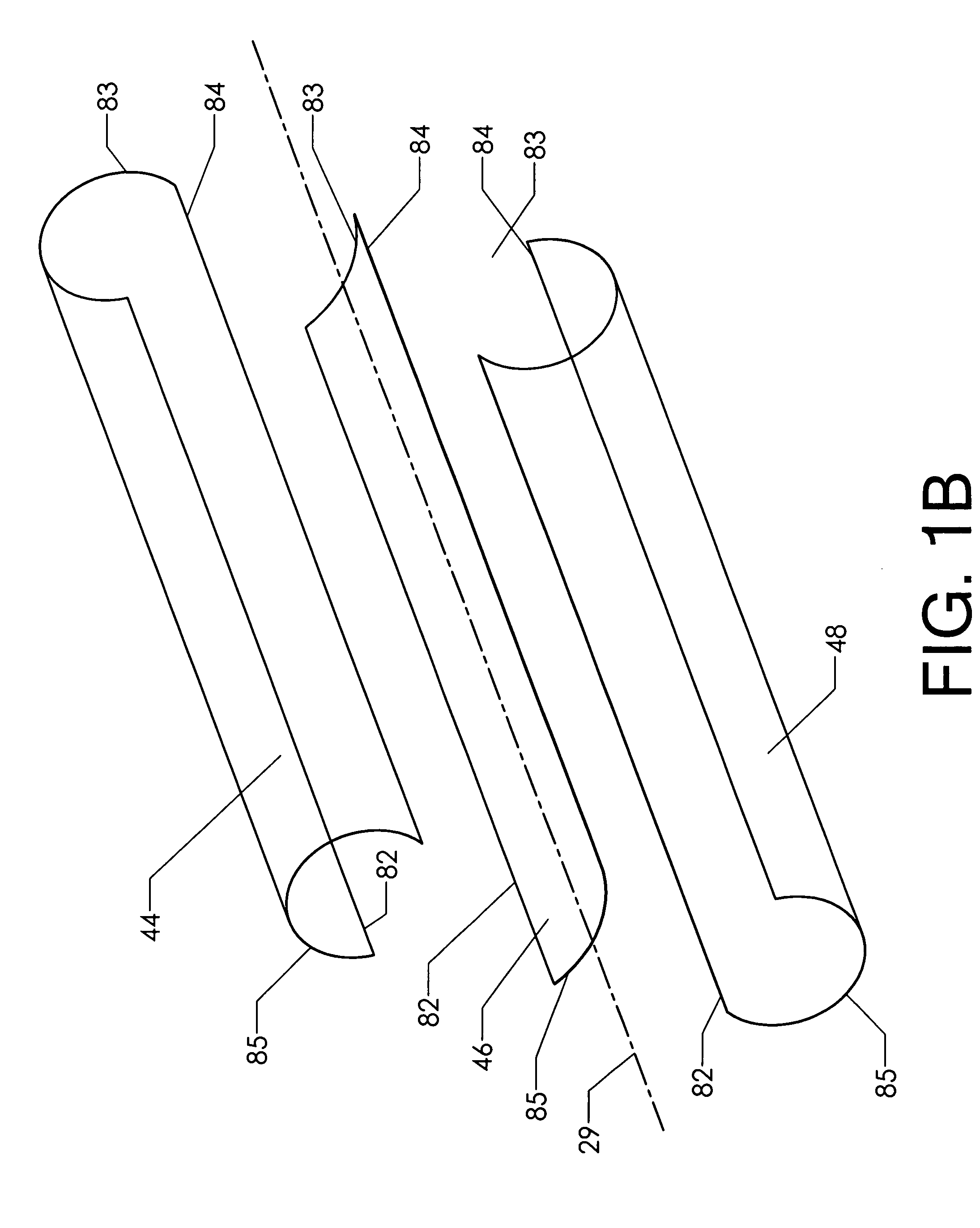
[0037]FIG. 1B is an exploded view of the three layers prior to their assembly. Each layer is made of a rectangular sheet of film. Each has a first edge 82, second edge 83, third edge 84, and fourth edge 85. The first and third ...


PUM


Abstract

An inflatable solar energy collector. The device uses two elongated and pressure-stabilized air chambers with a trough-shaped reflecting surface in between. The curvature of the reflecting surface is adjusted by adjusting the differential pressure between the two air chambers. The device can be configured to provide a focal point outside the air chambers or inside the air chambers. For the version using the external focal point an external energy receiver is appropriately positioned. For the version using the internal focal point, the receiver is mounted inside one of the air chambers.

Description

CROSS-REFERENCES TO RELATED APPLICATIONS[0001]This application claims the benefit pursuant to 37 C.F.R. §1.53(c) of an earlier-filed provisional application. The provisional application was filed on Apr. 18, 2008 and was assigned application Ser. No. 61 / 124:715. Ian L. Winger was listed as an inventor in the provisional application. Sean A. Barton is named as inventor for the first time in this submission.STATEMENT REGARDING FEDERALLY SPONSORED RESEARCH OR DEVELOPMENT[0002]Not Applicable.MICROFICHE APPENDIX[0003]Not ApplicableBACKGROUND OF THE INVENTION[0004]1. Field of the Invention[0005]This invention relates to the field of renewable energy. More specifically, the invention comprises an inflatable solar collector and associated components.[0006]2. Description of the Related Art[0007]Solar collectors are used to convert the sun's energy into a more useful form. There are two broad classes of collectors—those that create electricity using the photovoltaic effect and those which use...

Claims


Application Information

Patent Timeline
IPC IPC(8): F24J2/46G02B7/188F24S23/70F24S50/20
CPCF24J2/055H01L31/0547F24J2/506F24J2/51F24J2/5406F24J2/542F24J2002/5479Y02E10/44Y02E10/45Y02E10/47Y02E10/52G02B19/0042G02B19/0028G02B19/0033F24J2/145F24S80/60F24S80/525F24S2030/145F24S30/422F24S23/745F24S30/452F24S10/45F24S80/56
Inventor WINGER, IAN L.BARTON, SEAN A.
Owner FLORIDA STATE UNIV RES FOUND INC
Why Eureka
Try Eureka