Die casting mold and method of manufacturing and casting the same

a technology of die casting and molds, applied in the field of die casting molds, can solve the problems of lattice-patterned cracks on the inner surface of lattice-patterned cracks, heat checks, and surface defects of cast products, and achieve the effects of reducing preventing the occurrence of heat checks, and facilitating the repair of inserts

Active Publication Date: 2009-10-22
YAMAHA MOTOR CO LTD
View PDF0 Cites 8 Cited by
  • Summary
  • Abstract
  • Description
  • Claims
  • Application Information

AI Technical Summary

Benefits of technology

[0022]In order to overcome the problems described above, preferred embodiments of the present invention provide a die casting mold which reduces the occurrence of heat checks, a method of manufacturing the die casting mold which facilitates repairing of an insert, and a casting method which prevents the occurrence of heat checks, while enhancing the endurance and the number of casting cycles compared to the conventional art.

Problems solved by technology

This type of insert is used to repeat shots several thousand times in die casting operations, which causes a tendency for a cast product to have defects on the surface, which are called heat checks.
The cause of heat checks is that the lattice-patterned cracks are produced on the inner surface of the recessed cavity portion of the insert.
Cracks, a cause of the heat checks, are produced on the surface of the mold by repeated heating and cooling due to thermal stresses.
More specifically, cracks are produced due to thermal stresses that concentrate on a portion of the inner surface of the recessed cavity portion whose curvature is relatively large.
Such cracks are initially shallow and short.
In addition, in the event that it takes a longer time to repair the cast products, or the repair work is more difficult, due to larger heat checks or the increased number of locations where heat checks occur, the insert is repaired to eliminate the cracks or is replaced with a new one by a method to be discussed below.
Even if such a large-dimensioned insert is made of the optimum material and subjected to heat processing for enhanced hardness, there are still problems with heat checks that can occur in a relatively short time after the heat processing.
The potential cause of this is that the insert is not always subjected to heat processing entirely equally due to its relatively large size and volume, and accordingly, the cavity is not equally subjected to the heat processing.
This creates a problem of a significant increase in man-hours for removing the heat checks.
Further, even if the cracks on the inside of the recessed cavity portion, which can cause heat checks, are removed, there still arises a problem that the heat checks can re-occur in a relatively short time after the repair.
The reason for this is that the insert is repaired by removal of the cracks on the inside of the recessed cavity portion, and then build-up welding the cracked portion, which results in lower hardness and toughness on the build-up welded area compared to the other areas.
In contrast, the method, using the spacer to allow the large-dimensioned insert to protrude from the mold body and remove the protruding portion, fails to completely remove deep cracks largely due to the long time that elapses before the repair.
Therefore, the remaining minor cracks on the insert spread, causing heat checks in a short time after their removal.
This creates a problem of a longer time required for the cutting work.
In addition, in the case of replacing the insert with a new one, rather than refurbishing the insert, other usable portions of the cavity, such as the sprue portion, are also covered by this replacing, which results in an increased cost.

Method used


Image

  • Die casting mold and method of manufacturing and casting the same
  • Die casting mold and method of manufacturing and casting the same
  • Die casting mold and method of manufacturing and casting the same

Examples


Embodiment Construction

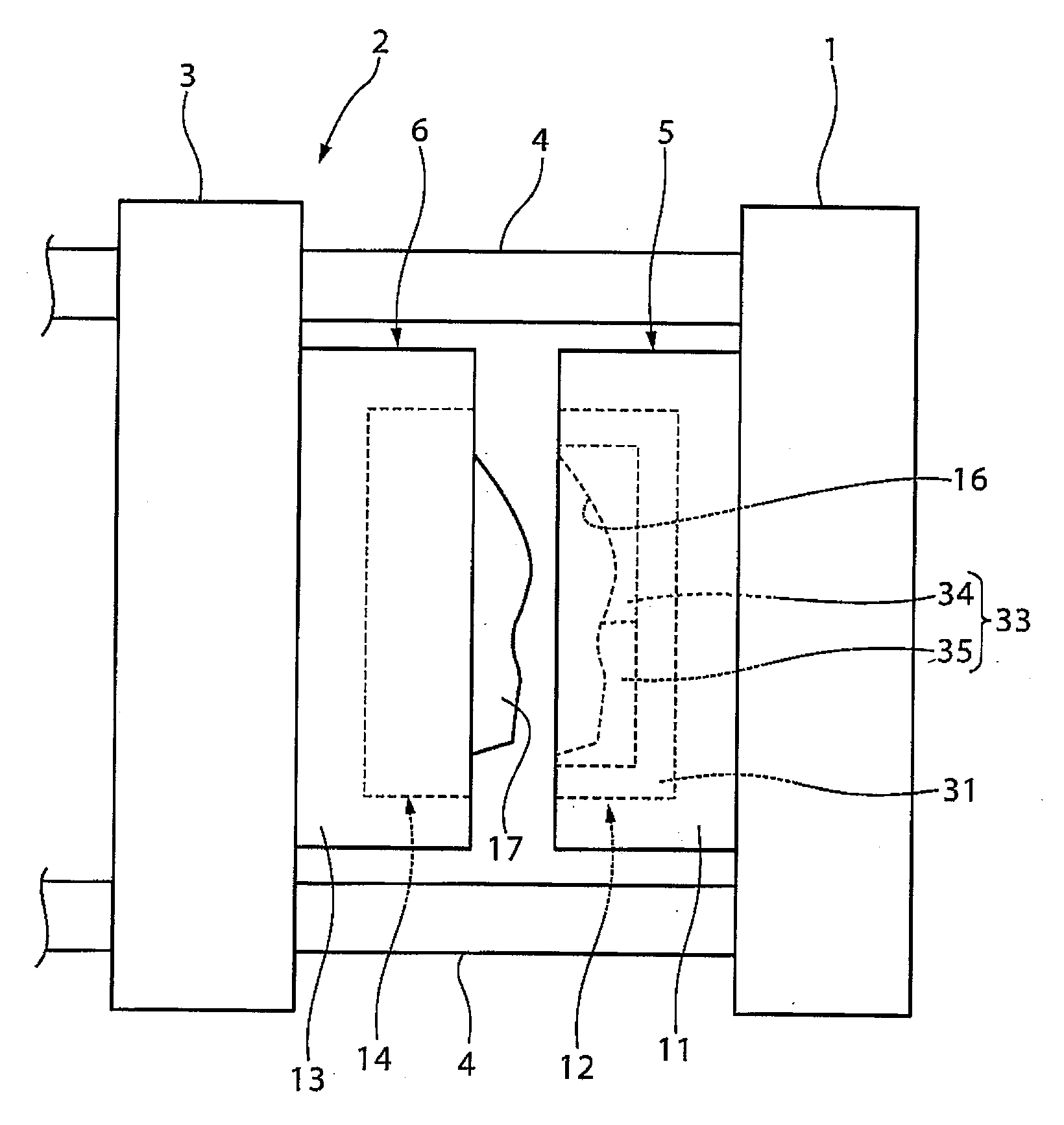
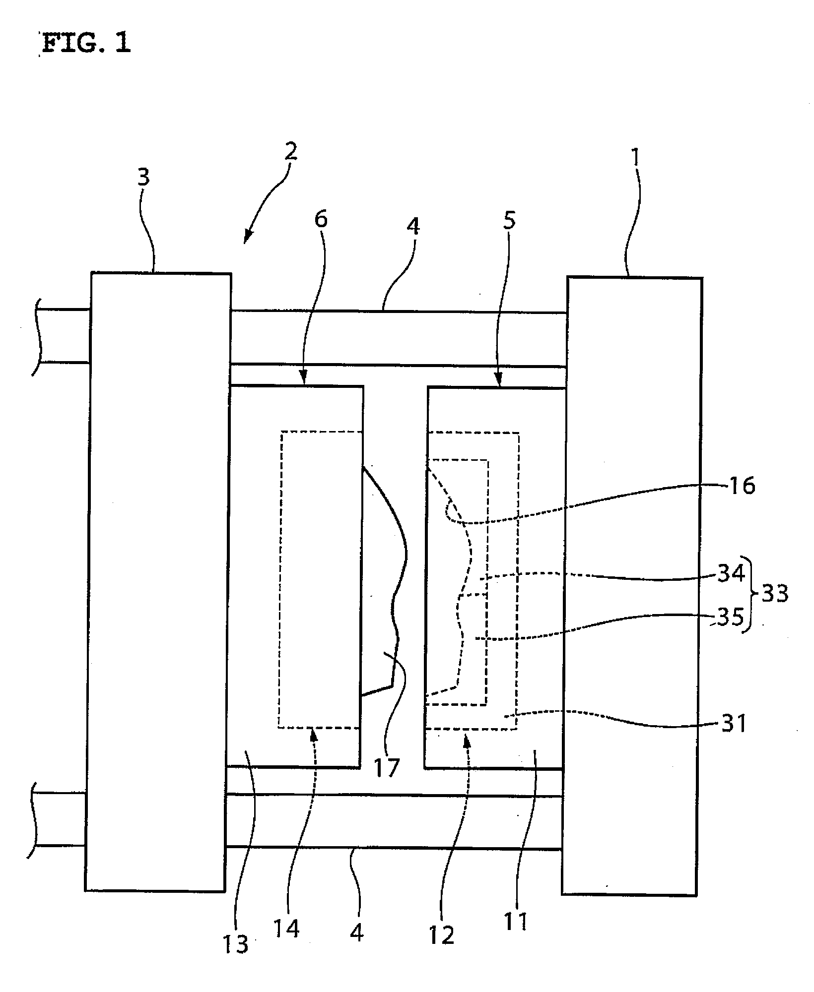
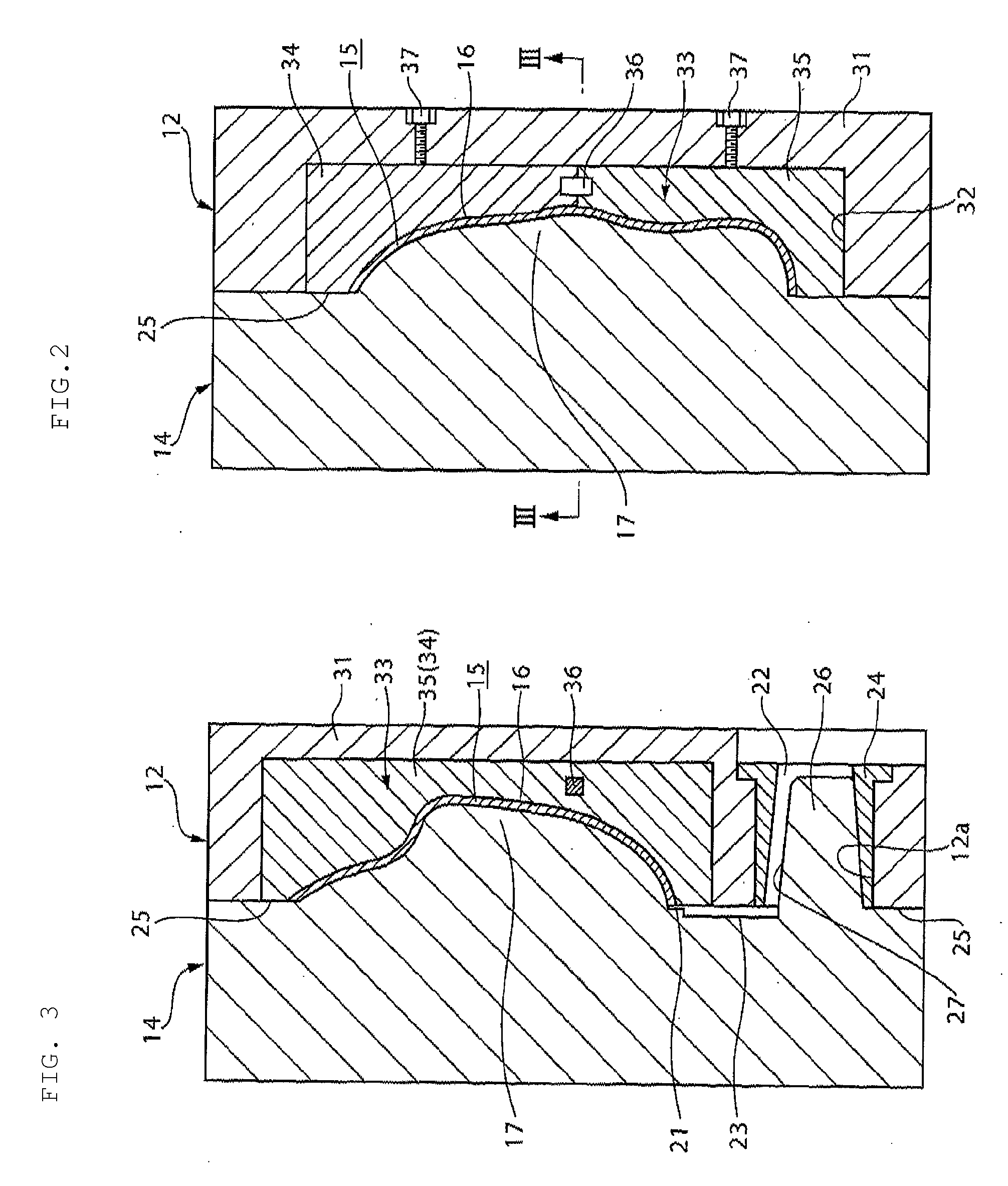
[0034]Preferred embodiments of a die casting mold according to the present invention and a preferred method of manufacturing the same will be described below in detail with reference to FIG. 1 to FIG. 7.

[0035]In the figures, reference numerals 1, 3, and 4 denote a fixed platen, a movable platen, and tie bars of a die casting machine 2, respectively. The fixed platen 1 is fixed to a base (not shown) of the die casting machine 2. The movable platen 3 is designed to move by a drive unit (not shown) on the base in the horizontal direction parallel to the tie bars 4.

[0036]A fixed mold 5, or the die casting mold according to the various preferred embodiments of the present invention, is assembled to the fixed platen 1. A movable mold 6, which may be clamped to the fixed mold 5, is assembled to the movable platen 3. In FIG. 1 to FIG. 5, an extrusion pin provided on the movable mold 6, a drive unit for the extrusion pin, cooling water passages provided on both of the molds 5 and 6, a mold c...


PUM

PropertyMeasurementUnit
thicknessaaaaaaaaaa
hardnessaaaaaaaaaa
toughnessaaaaaaaaaa

Abstract

In a die-casting mold used in a casting method, a fixed insert includes a recessed cavity portion, and a fixed mold body is arranged to hold the fixed insert. The fixed insert includes a first insert and a second insert. The first insert is held with the fixed mold body. The second insert is fitted and held within a recess formed on the first insert. The size of the second insert is minimized so as to just surround the recessed cavity portion.

Description

BACKGROUND OF THE INVENTION[0001]1. Field of the Invention[0002]The present invention relates to a die casting mold in which a recessed cavity portion is provided on an insert, and relates to a method of manufacturing and casting the die casting mold.[0003]2. Description of the Related Art[0004]A conventional die casting mold of the above-described type is disclosed, for example, in JP-B-Hei 7-73783. The mold described in this publication includes a fixed mold attached to a fixed platen of a die casting machine, and a movable mold attached to a movable platen thereof.[0005]The fixed mold includes a fixed insert, on which a recessed portion defining a cavity is provided, and a mold body for holding the fixed insert. The movable mold includes a movable insert that has a projecting portion facing the recessed portion which forms the cavity in cooperation with the fixed insert, and a mold body for holding the movable insert.[0006]As described above, the mold which is divided into the in...

Claims


Application Information

Patent Timeline
Patent Type & Authority Applications(United States)
IPC IPC(8): B22C9/00B22D17/00B22D45/00
CPCB22D17/22B22C9/06
Inventor YOSHII, HIROSHISATOU, KIMITOSHIINAMURA, TAKAYOSHI
Owner YAMAHA MOTOR CO LTD
Why Eureka
Try Eureka