Discharge lamp exhibiting reduced thermal stress and method of making such a lamp

a technology of discharge lamp and thermal stress, which is applied in the manufacture of electric discharge tube/lamp, cold cathode, and electromechanical system, etc., can solve the problems of increasing the cost of the lamp, adding parts and costs, and achieving reduced thermal conductivity, reduced lamp cost, and higher electrical resistance

Inactive Publication Date: 2009-10-22
LEDVANCE LLC
View PDF8 Cites 2 Cited by
  • Summary
  • Abstract
  • Description
  • Claims
  • Application Information

AI Technical Summary

Benefits of technology

[0008]These objects are accomplished, in one aspect of the invention, by the provision of a discharge lamp comprising: an outer envelope; first and second electrical lead-ins sealed into the base of the envelope; a ceramic arc tube operatively mounted within the envelope, the arc tube having at least one electrode therein; a tubular, niobium feed-through connected to the at least one electrode and sealed to the ceramic body; and a stainless steel rod electrically connected between a first of the electrical lead-ins and the tubular niobium feed-through, the stainless steel rod being the only electrical connection between the lead-in and the niobium feed-through. The difficulty of achieving a good, long-lasting weld between the niobium and the stainless steel (necessary because a suitable stainless steel, such as 430SS, has a lower thermal conductivity and higher electrical resistance then the previously employed NPS) is surmounted by a new welding method that involves adding an argon shield gas to the welding station. The elimination of what was previously considered to be an indispensable component has reduced the cost of the lamp and the consummation of a better connection with a more suitable support structure has greatly enhanced and improved the lamp.

Problems solved by technology

However, while this technique worked successfully, it added parts and cost to the lamp.
Further, it would be an advance in the art to eliminate the NPS support because the nickel plating process is not environmentally friendly and, as fewer and fewer companies undertake its manufacture, its cost has greatly increased.

Method used


Image

  • Discharge lamp exhibiting reduced thermal stress and method of making such a lamp
  • Discharge lamp exhibiting reduced thermal stress and method of making such a lamp
  • Discharge lamp exhibiting reduced thermal stress and method of making such a lamp

Examples


Embodiment Construction

[0011]For a better understanding of the present invention, together with other and further objects, advantages and capabilities thereof, reference is made to the following disclosure and appended claims taken in conjunction with the above-described drawings.

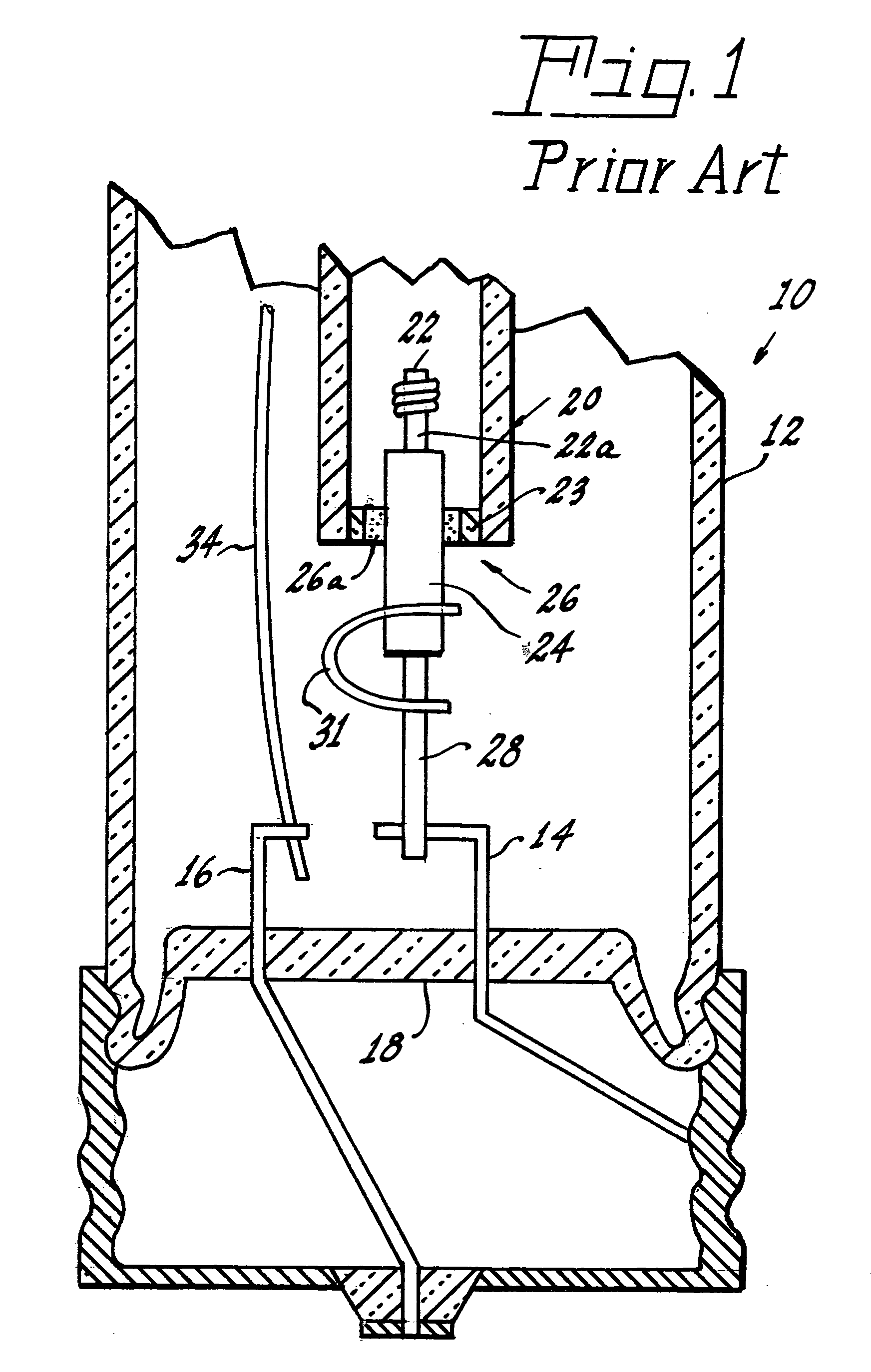
[0012]Referring now to the drawings with greater particularity, there is shown in FIG. 1 a prior art high pressure sodium lamp 10 having a vitreous outer envelope 12.

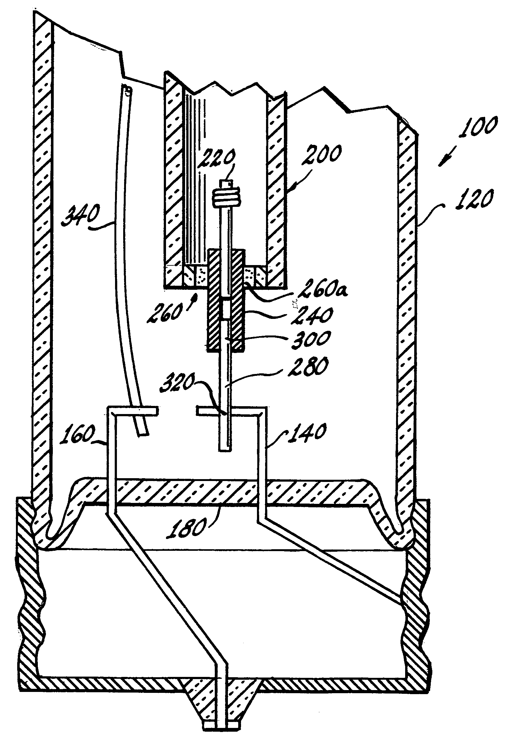
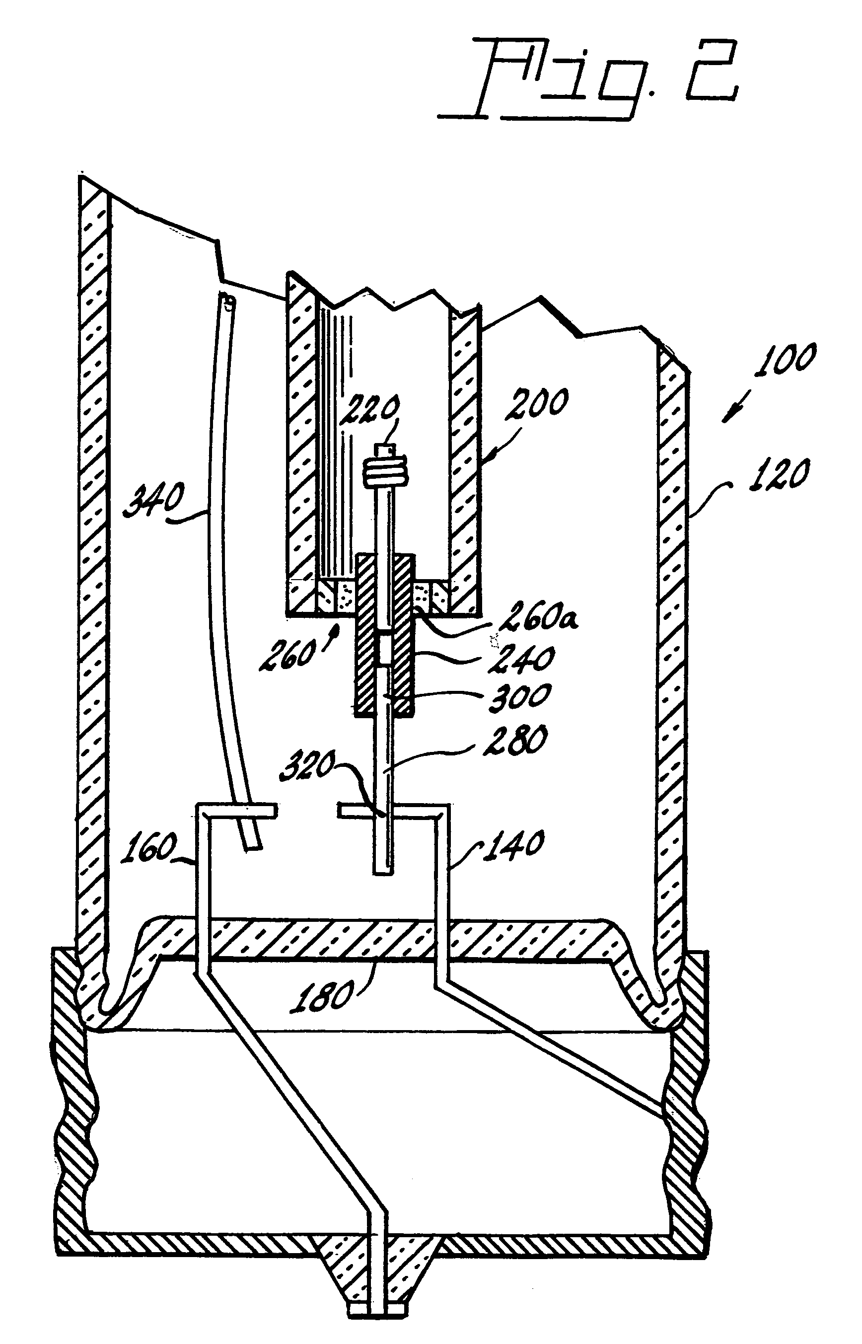
[0013]Lead-ins 14, 16 are sealed into the base 18 of the envelope. A ceramic arc tube 20, for example, one constructed of polycrystalline alumina, is mounted in the outer envelope 12. Electrodes 22 (only one of which is shown) are sealed into opposite ends of the arc tube 20 by known techniques. For example, the electrode 22 can be a tungsten rod 22a sealed into a niobium tube 24. The niobium tube 24 is itself hermetically sealed into a ceramic endcap 23 by a joint 26 that comprises a glass frit 26a. A support rod 28, such as one of NPS, is fitted into the niobium tu...


PUM

PropertyMeasurementUnit
electricalaaaaaaaaaa
pressureaaaaaaaaaa
thermal expansion coefficientaaaaaaaaaa

Abstract

A lamp (100) comprises an outer envelope (120) having first and second electrical lead-ins (140, 160) sealed into a base (180) of the envelope (120). A ceramic arc tube (200) is operatively mounted within the envelope (120), the arc tube (200) having at least one electrode (220) therein. A tubular, niobium feed-through (240) is connected to the at least one electrode (220) and sealed to the ceramic body (120) at a joint (260) that can comprise a glass frit (260a). A stainless steel rod (280) is electrically connected between the electrical lead-in (140) and the tubular niobium feed-through (240), the stainless steel rod (280) being the only electrical connection between the lead-in (140) and the niobium feed-through (240).

Description

TECHNICAL FIELD[0001]This invention relates to discharge lamp. More particularly it relates to discharge lamps having ceramic arc tubes and still more particularly it relates to high pressure sodium discharge lamps.BACKGROUND ART[0002]Discharge lamps, such as the afore-mentioned sodium lamps, are staple articles of commerce. The lamps comprise a ceramic arc tube mounted in a vitreous envelope and various electrical lead-ins to conduct current to the arc tube electrodes. Because of the different materials used, such as the ceramic arc tube and various metallic components and their differing thermal expansion coefficients (TEC), many compromises have to be made to ensure economic manufacturing costs, reasonable light output and reasonable life expectancy.[0003]Anytime any of these contingencies can be enhanced or improved, a decided advance in the art is achieved. For example, in high pressure sodium lamps it has been necessary to provide an auxiliary, U-shaped, current-carrying niobi...

Claims


Application Information

Patent Timeline
Patent Type & Authority Applications(United States)
IPC IPC(8): H01J17/16H01J9/02
CPCH01J61/36H01J61/825H01J61/366
Inventor BOURGERY, MATTHEW A.TOWNSEND, PAUL H.CHAO, CHUNG-YAO
Owner LEDVANCE LLC
Why Eureka
Try Eureka