Phase-control dimming electronic ballast system and control method thereof

a technology of electronic ballast system and phase control, which is applied in the direction of lighting apparatus, light sources, instruments, etc., can solve the problems of increasing wiring load, unnecessary energy consumption, and extra load, and achieves non-zero power switching, improving the problem of poor light dimming feature, and expanding the dimming range

a technology of electronic ballast system and phase control, which is applied in the direction of lighting apparatus, light sources, instruments, etc., can solve the problems of increasing wiring load, unnecessary energy consumption, and extra load, and achieves non-zero power switching, improving the problem of poor light dimming feature, and expanding the dimming range

US20090261744A1Inactive Publication Date: 2009-10-22FEGO PRECISION INDAL

Image

  • Phase-control dimming electronic ballast system and control method thereof
  • Phase-control dimming electronic ballast system and control method thereof
  • Phase-control dimming electronic ballast system and control method thereof

Examples


Embodiment Construction

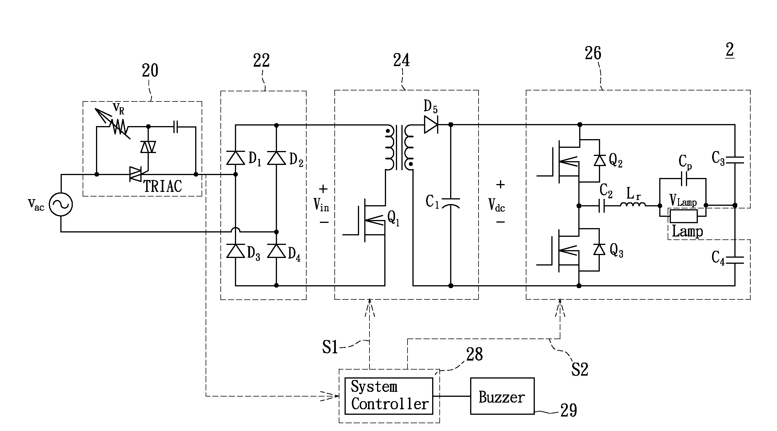
[0036]Refer now to FIG. 2, wherein a system block diagram of a phase-control dimming electronic ballast system according to the present invention is shown. The phase-control dimming electronic ballast system 2 of the present invention is used to linearly adjust the brightness of a fluorescent lamp, wherein the phase-control dimming electronic ballast system 2 comprises a phase controller 20, a rectifier 22, a converter 24, an inverter 26 and a system controller 28.

[0037]Referring again to FIG. 2, the phase controller 20 comprises a variable resistor VR and a thyristor based TRIAC, in which the phase controller 20 changes the thyristor based TRIAC by adjusting the variable resistor VR, triggering an AC voltage Vac on each half cycle of the phase firing angle α, so as to further adjust the magnitude of the AC voltage Vac based on the phase firing angle α. Meanwhile, the rectifier 22 is coupled to the phase controller 20, acquiring adjusted AC voltage Vac from the phase controller 20, ...


PUM


Abstract

A phase-control dimming electronic ballast system and the control method thereof, wherein the system includes a phase controller, a converter, an inverter and a system controller. Moreover, the system controller senses a firing angle from the phase controller, and adjusts the output voltage of the converter and the switching frequency of the inverter to achieve the operation of dimming fluorescent lamp.

Description

BACKGROUND OF THE INVENTION[0001]1. Field of the Invention[0002]The present relates to a phase-control dimming electronic ballast system and control method thereof; in particular, to a control system and control method thereof for linear light dimming of a fluorescent lamp by means of detecting the phase firing angle of an input power.[0003]2. Description of Related Art[0004]In today's age, demand for lighting is not merely limited to whether the lighting is sufficient, but also needs to consider the ability for lighting adjustment based on the environmental requirements, as well as reduction of unnecessary energy consumption, thus the development of adjustable lighting system has now become desirable.[0005]Currently, the approaches for fluorescent lamp lighting adjustment comprise frequency modulation, voltage modulation and duty cycle modulation. FIG. 1A shows an architectural diagram of a frequency modulation light dimming electronic ballast system. FIG. 1B shows an architectural...

Claims


Application Information

Patent Timeline
22 Oct 2009
Publication
US20090261744A1
IPC
H05B37/02
CPC
H05B41/3925
Inventors
CHEN, YU-KAI; WU, YUNG CHUN