Light source unit and projector

Active Publication Date: 2009-10-22
CASIO COMPUTER CO LTD
View PDF8 Cites 80 Cited by
  • Summary
  • Abstract
  • Description
  • Claims
  • Application Information

AI Technical Summary

Benefits of technology

[0015]The invention has been made in view of the problem inherent in the related-art and an object thereof is to provide a projector which c

Problems solved by technology

Compared with discharge lamps, light emitting diodes are advantageous in that they consume less power and highly reliable However, the amount of light emitted by a single light emitting diode is still not good enough for use as a light source for a projector, leading to a problem that a desired luminance cannot be obtained.
However, when the value of the Etendue of the light source unit which is expressed by S×Ω is larger than the value of the Etendue of the display device which is expressed by S′×Ω′, there occurs a situation in which some of the light emitted form the light source unit cannot be used.
However, when the plurality of diodes are used, since the light emitting area becomes large, the value of the Eten

Method used


Image

  • Light source unit and projector
  • Light source unit and projector
  • Light source unit and projector

Examples


Example

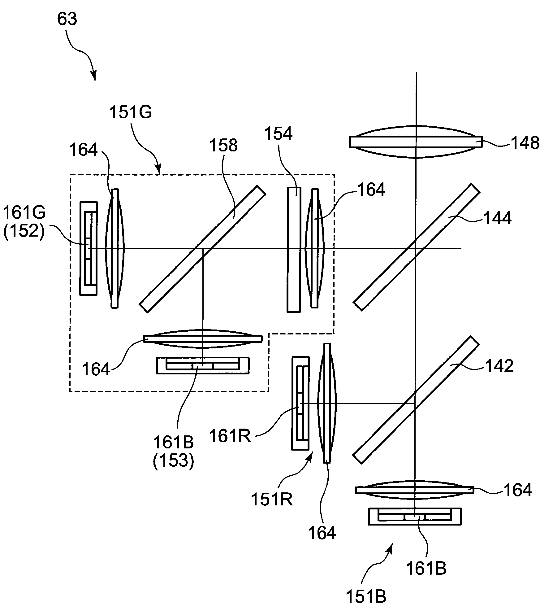
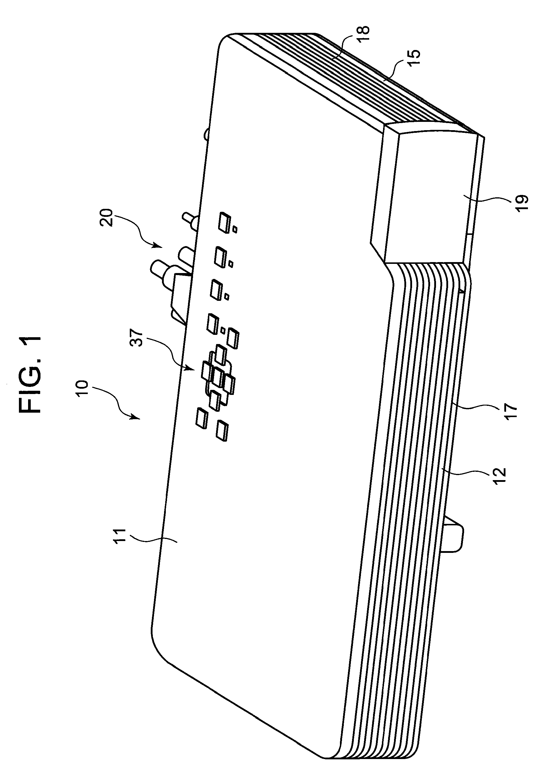
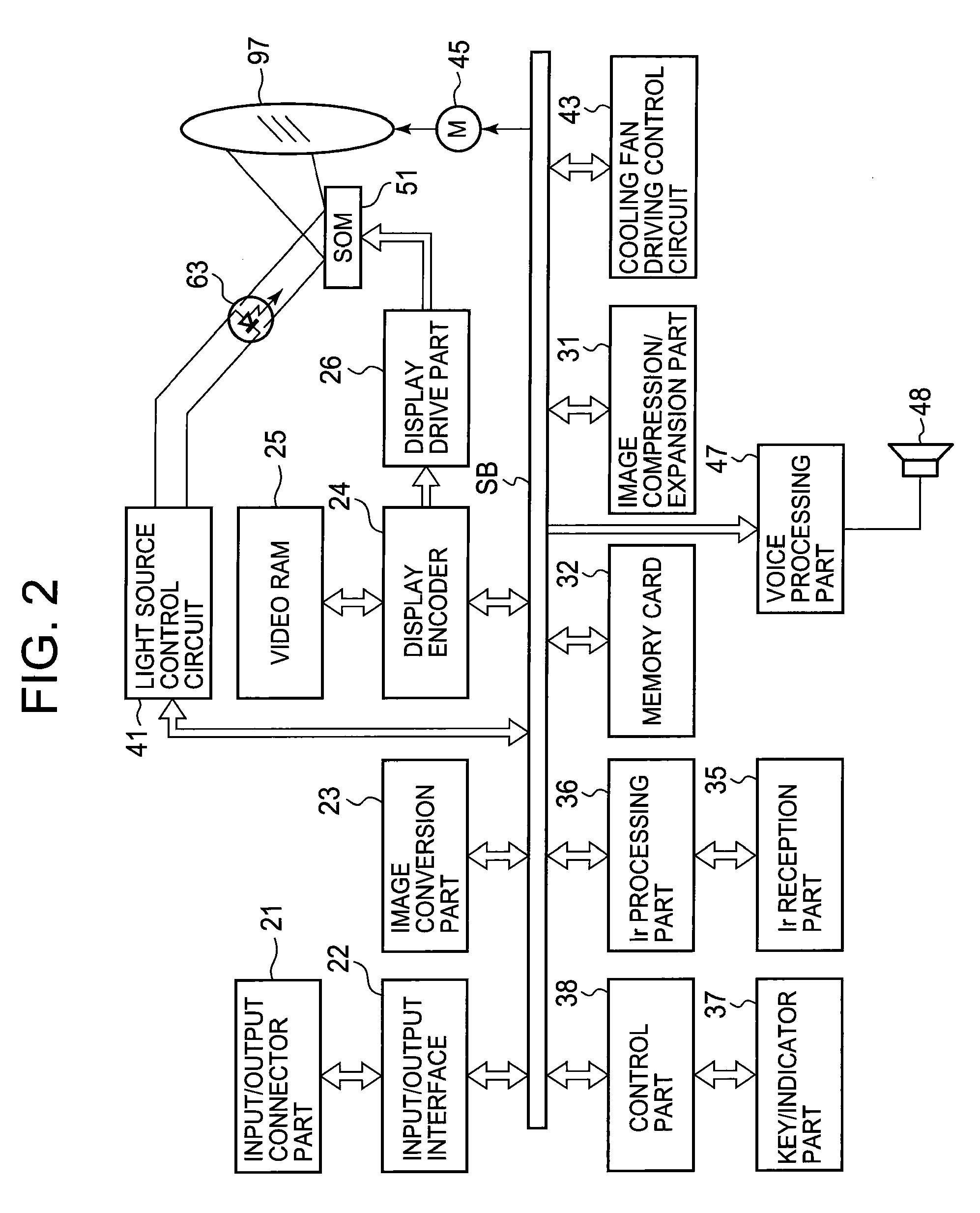
[0023]A projector 10 according to a best mode for carrying out the invention includes a light source unit 63, a light guiding unit or light smoothing unit 75, a display device 51, a projection side optical system 90, and a projector control unit.

[0024]The light source unit 63 includes three light source devices having specific wavelength bands such as a red light source device 151R which employs red light emitting diodes 161R which emit red light, a green light source device 151G which emits green light and a blue light source device 151B which employs blue light emitting diodes 161B which emit blue light. The green light source device 151G includes a first light source 152 which is formed by a plurality of green light emitting diodes 161G which emit single-color light of green and, in addition thereto, a second light source 153 which is formed by a plurality of blue light emitting diodes 161B which emit excitation light and a third light source 154 which is formed by a board-like l...


PUM


Abstract

In a projector which includes a light source unit 63, a light smoothing unit, a display device, a projection side optical system and a projector control unit, the light source unit 63 includes a light generating device for generating light of a specified wavelength band which includes a first light source 152 which is a light emitting diode or solid-state light emitting device for emitting light of a predetermined wavelength band, a second light source 153 which is a light emitting diode or a solid-state light emitting device for emitting excitation light, and a third light source 154 for emitting light of the same wavelength band as that of the first light source 152 using the light emitted from the second light source 153 as excitation energy, and the third light source 154 is formed by a phosphor which transmits light from the first light source 152 and absorbs light emitted from the second light source 153.

Description

CROSS-REFERENCE TO RELATED APPLICATIONS[0001]This application is based upon and claims the benefit of priority under 35 USC 119 of Japanese Patent Application No. 2008-106884 filed on Apr. 16, 2008, the entire disclosure of which, including the description, claims, drawings, and abstract, is incorporated herein by reference in its entiretyBACKGROUND OF THE INVENTION[0002]1. Field of the Invention[0003]The present invention relates to a light source unit which employs light emitting diodes or solid state light emitting devices and a projector which includes the light source unit.[0004]2. Description of the Related Art[0005]In these days, data projectors are used in many cases as an image projection apparatus for projecting screens and video images of a personal computer and, further, images based on image data stored in a memory card onto a screen. In projectors of this type, light emitted from a light source is concentrated on to a micromirror display device referred to as a DMD or ...

Claims


Application Information

Patent Timeline
IPC IPC(8): G03B21/14F21V9/00
CPCF21V9/00G03B21/14F21Y2101/02G03B21/145G03B21/2033G03B33/12F21Y2115/10F21V9/20
Inventor OGAWA, MASAHIRO
Owner CASIO COMPUTER CO LTD
Why Eureka
Try Eureka