Supercharge Your Innovation With Domain-Expert AI Agents!

DLL circuit with wide-frequency locking range and error-locking-avoiding function

a technology of error-locking and dll circuit, which is applied in the direction of digital transmission, generator starter, pulse automatic control, etc., can solve the problems of inconvenient user and huge error

Inactive Publication Date: 2009-10-22
ETRON TECH INC
View PDF1 Cites 0 Cited by
  • Summary
  • Abstract
  • Description
  • Claims
  • Application Information

AI Technical Summary

Benefits of technology

[0011]The present invention provides a delay-locked loop circuit with wide frequency locking range and error-locking avoiding function, for generating a delayed locking periodic signal according to a reference periodic signal, the delay-locked loop circuit comprises a phase/frequency detector, a voltage controller, a voltage controlled delay circuit, a predetermined delay circuit, an adjustable delay circuit, a first switch, a second switch, and a third switch. The phase/frequency detector, comprises a first input terminal for receiving the reference periodic signal; a second input terminal; a first output terminal, wherein the phase/frequency detector outputs a first controlling signal via the first output terminal of the phase/frequency detector according to signals at the first input terminal and the second input terminal of the phase/frequency detector; and a second output terminal, wherein the phase/frequency detector outputs a second controlling signal via the second output terminal of the phase/frequency detector according to signals at the first input terminal and the second input terminal of the phase/frequency detector. The voltage controller coupled to the first and the second output terminals of the phase/frequency detector, the voltage controller outputs a corresponded voltage level according to the first controlling signal or the second controlling signal. The voltage controlled delay circuit comprises: an input terminal for receiving the reference periodic signal; a control terminal coupled to the output terminal of the voltage controller; and an output terminal, wherein the voltage controlled delay circuit delays the received reference periodic signal according to the corresponded level voltage outputted from the voltage cont

Problems solved by technology

This is because the slightly variation of the voltage VX may greatly change the delay DX and to consequently result a huge error.
Accordingly, the conventional DLL circuit 100 limits options for the reference periodic signal CLKREF and the delay phase, which is greatly inconvenient for the user.

Method used


Image

  • DLL circuit with wide-frequency locking range and error-locking-avoiding function
  • DLL circuit with wide-frequency locking range and error-locking-avoiding function
  • DLL circuit with wide-frequency locking range and error-locking-avoiding function

Examples


Embodiment Construction

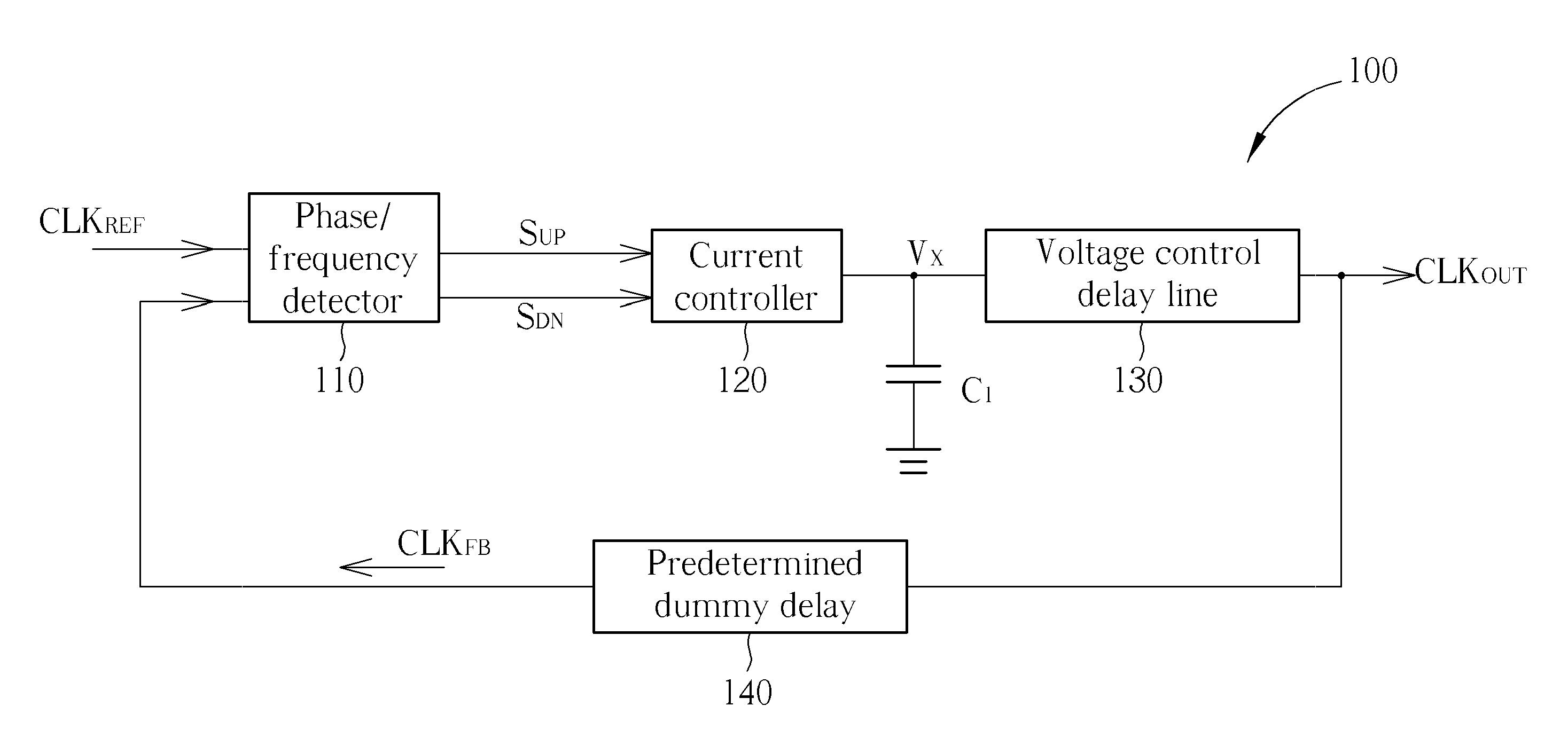
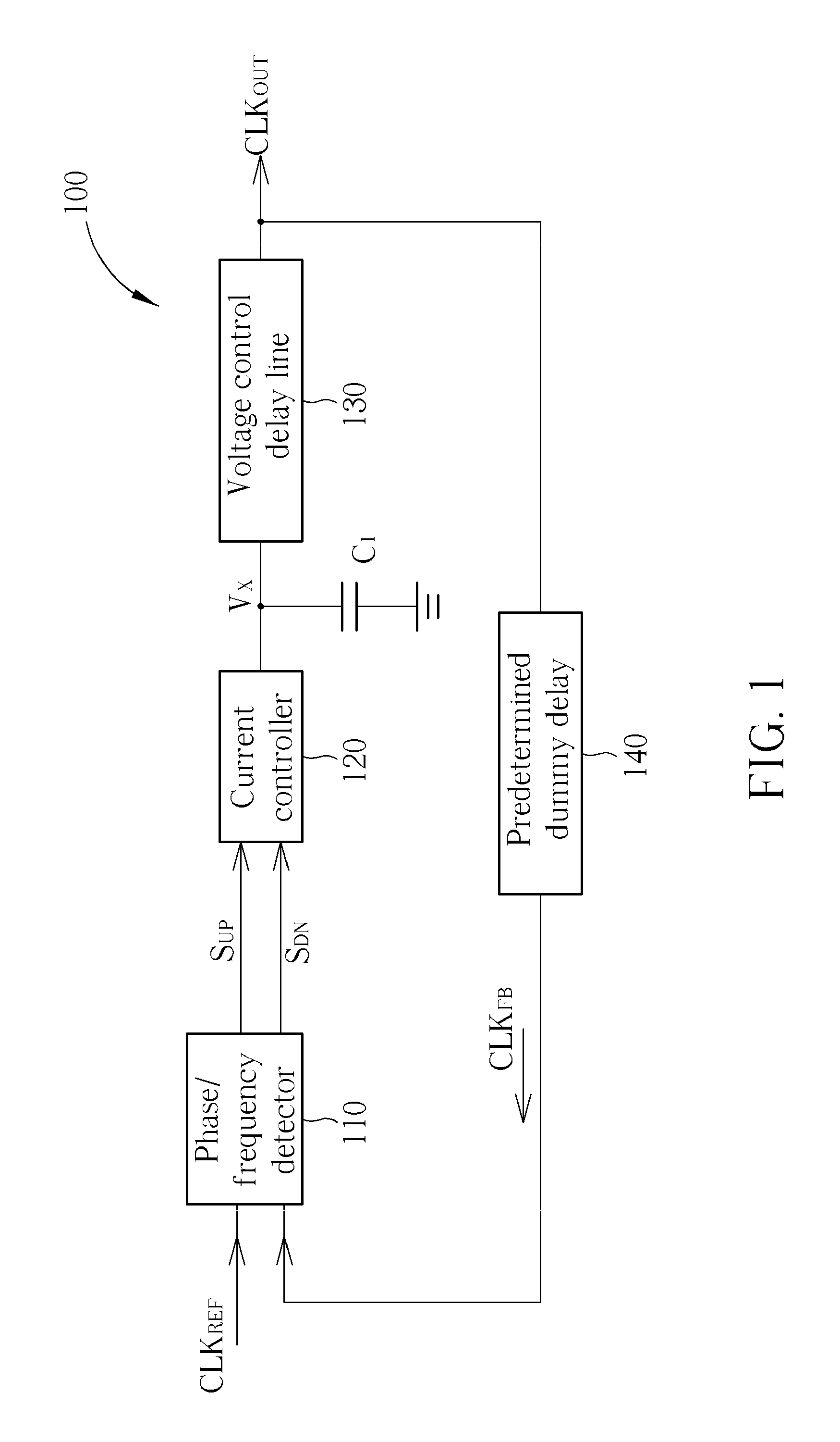
[0021]Please refer FIG. 4. FIG. 4 is a diagram illustrating a DLL circuit 400 according to an embodiment of the present invention. The delay lock loop circuit 400 comprises a phase / frequency detector 410, a voltage controller 421, a startup voltage charging circuit 423, a voltage controlled delay circuit 430, three switches SW1, SW2, and SW3, a predetermined delay circuit 440, a duty cycle correction (DCC) circuit 450, an adjustable delay circuit 460, and a frequency divider 470.

[0022]Please continue referring to FIG. 4. The phase / frequency detector 410 comprises two input terminals for respectively receiving a reference periodic signal CLKREF and a feedback periodic signal CLKFB that have been divided by the frequency divider 470. Please note that, a divisor of the frequency divider 470 is set to one for brevity. In other words, the reference periodic signal CLKREF and the feedback periodic signal CLKFB that after being divided by the frequency divider 470 are same as the original ...


PUM


Abstract

A delay-locked loop (DLL) circuit. In the evaluation period, the DLL circuit adjusts needed delay period of time for a reference clock signal by adjusting the amount of the used delay units which each of has fixed delay period of time digitally and controlling the delay period of time of the voltage control delay circuit analogically. In the locking period, the DLL circuit utilizes the delay time of the delay units, which is decided in the evaluation period, along with the voltage control delay circuit, to lock phase of the reference clock signal. In this way, the stability of the delay period of time of the voltage control delay circuit increases.

Description

BACKGROUND OF THE INVENTION[0001]1. Field of the Invention[0002]The present invention relates to a delay-locked loop circuit, and more particularly, to the delay-locked loop circuit having wide frequency locking range and error-locking-avoiding function.[0003]2. Description of the Prior Art[0004]Please refer to FIG. 1. FIG. 1 is a diagram illustrating a conventional delay-locked loop (DLL) circuit 100. The DLL circuit 100 comprises a phase / frequency detector 110, a current controller 120, a capacitor C1, a voltage control delay line (VCDL) 130, and a predetermined dummy delay 140.[0005]Please continue referring to FIG. 1. The phase / frequency detector 110 comprises two input terminals for receiving a reference periodic signal CLKREF and a feedback periodic signal CKLFB respectively. The phase / frequency detector 110 determines the phase difference between the reference periodic signal CLKREF and the feedback periodic signal CKLFB and accordingly outputs the control signals SUP or SDN....

Claims


Application Information

Patent Timeline
IPC IPC(8): H03D3/24
CPCH03L3/00H03L7/0812H03L7/10H03L7/093H03L7/0814
Inventor HUANG, HSIEN-SHENG
Owner ETRON TECH INC
Features
  • R&D
  • Intellectual Property
  • Life Sciences
  • Materials
  • Tech Scout
  • Unparalleled Data Quality
  • Higher Quality Content
  • 60% Fewer Hallucinations
Learn More