Friction-Release Distal Latch Implant Delivery System and Components

a technology of distal latch and delivery system, which is applied in the field of distal latch implant delivery system and components, can solve the problems of inadvertent deployment and/or non-optimal control, limited system miniaturization of referenced system(s), and inability to meet the needs of patients, etc., and achieve the effect of lengthwise shortening of the implan

Inactive Publication Date: 2009-10-22
TYCO HEALTHCARE GRP LP
View PDF8 Cites 80 Cited by
  • Summary
  • Abstract
  • Description
  • Claims
  • Application Information

AI Technical Summary

Benefits of technology

[0010]The tubular implant is expandable from a contracted state to an expanded state, and preferably self-biased towards the expanded state. Generally, expansion results in lengthwise shortening of the implant. Thus, holding the end portions of the implant stretched apart from each other (such as in the state of frictional lock described herein) can cause the implant to be maintained in a contracted state, without the need to radially restrain the entire implant (such as with a full body sheath). If the implant is self-biased to expand, release of the end portions allows the implant to expand into apposition with tissue at the implantation site. Else, a secondary expansion device can be used, such as an inflatable balloon or mechanical arms.
[0011]The frictional lock described herein relies on a high degree of surface friction between the implant and an underlying surface to resist longitudinal / axial motion of the implant (in its contracted state) along the longitudinal axis of the delivery device or sleeve. Substantial surface friction between implant and the underlying surface will prevent the implant from sliding relative to the underlying surface, preventing the implant from decreasing in length (i.e., for shortening) and radially expanding.

Problems solved by technology

System miniaturization of the referenced system(s) is limited by the gripper configuration.
Also, the lack of a release mechanism for detachment from the distal socket presents issues of inadvertent deployment and / or non-optimal control.
Generally, expansion results in lengthwise shortening of the implant.

Method used


Image

  • Friction-Release Distal Latch Implant Delivery System and Components
  • Friction-Release Distal Latch Implant Delivery System and Components
  • Friction-Release Distal Latch Implant Delivery System and Components

Examples


Embodiment Construction

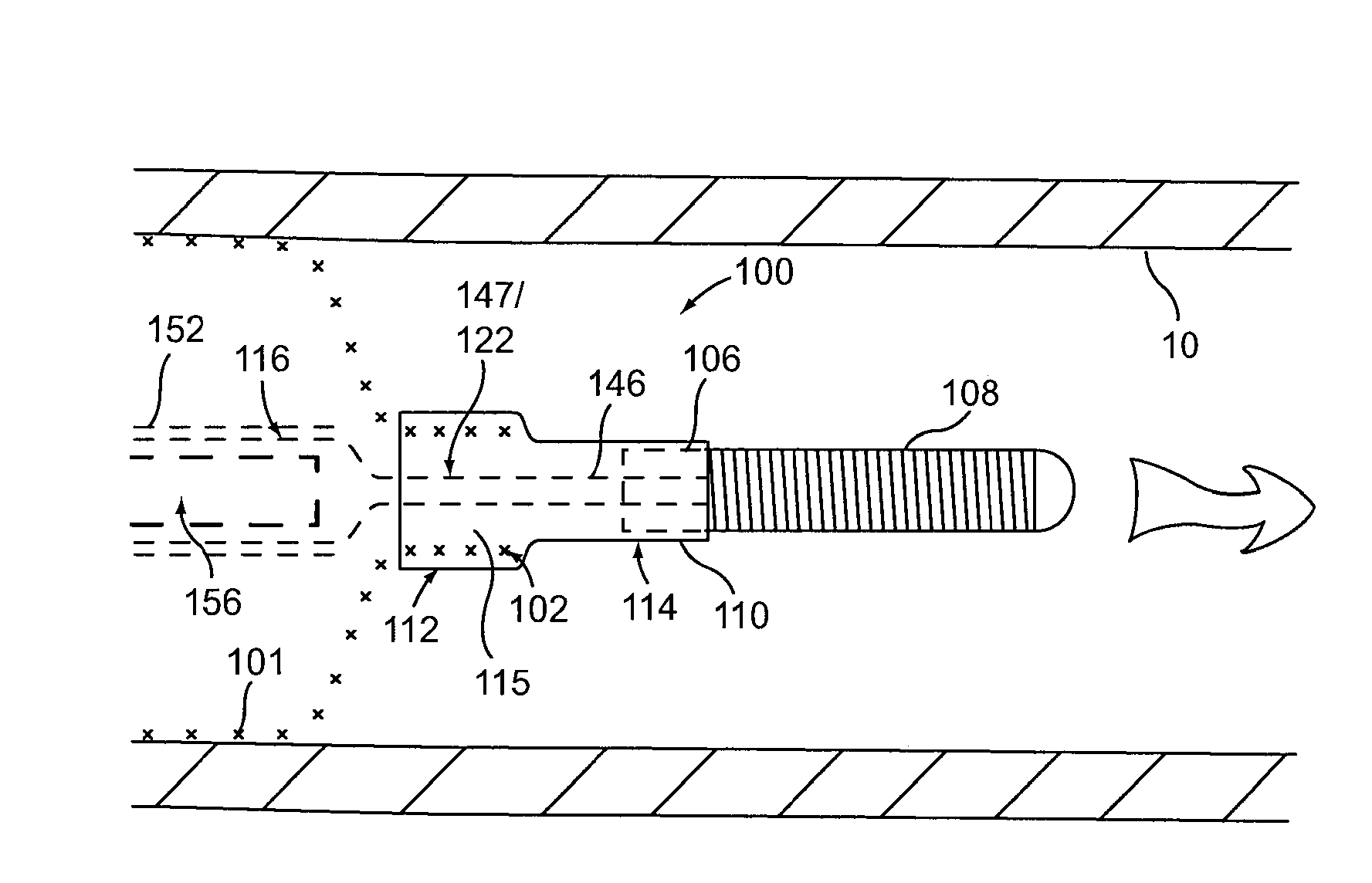
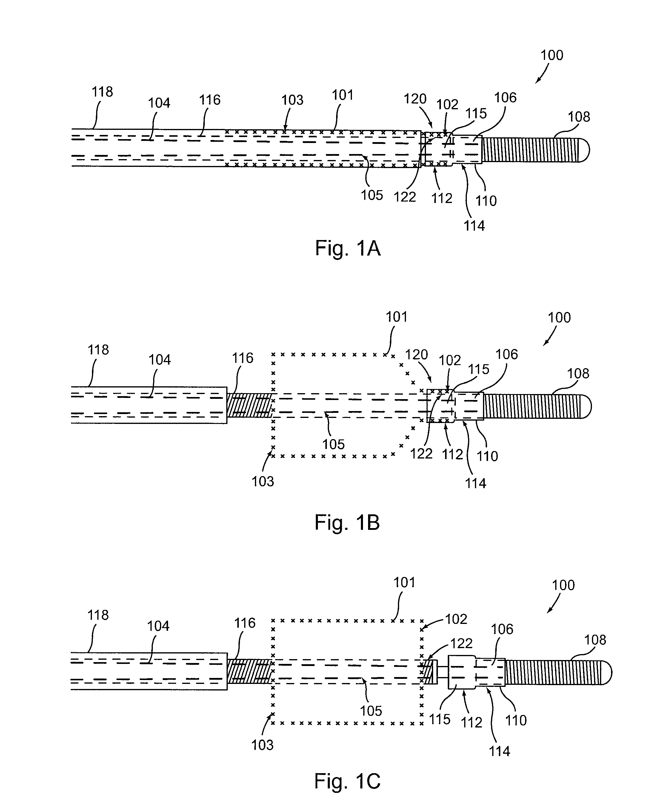
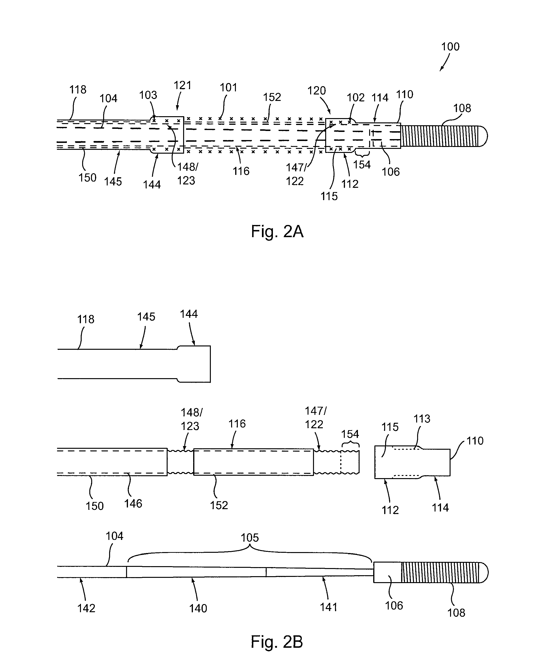
[0032]Provided herein are systems, devices and methods for the delivery of a preferably expandable implant using one or more devices for releasably holding the implant in a state of frictional lock.

[0033]Turning to FIG. 1A, a tubular implant 101 is held in a contracted state in the implant delivery system 100. System 100 includes an elongate tubular proximal member (or outer sheath) 118. An elongate core member 104 and an elongate textured member 116 are both located within the lumen of outer sheath 118. Elongate textured member (or sleeve) 116 is configured as a tubular sleeve with the elongate core member 104, which is preferably a wire or wire-like member, slidable within the lumen of sleeve 116. Core member 104 is coupled to a hub 106 at its distal end, as well as an atraumatic tip 108, depicted here as a coiled floppy tip. Alternatively, the coil tip 108 may be omitted and core member 104 can instead be tubular (e.g., comprising hypo-tube) to allow for over-the-wire system use....


PUM


Abstract

Provided herein are systems, devices and methods for the delivery of medical implants. A distal end portion of the implant is coupled with a delivery device by surface friction between the implant and an underlying surface such that the distal end portion is frictionally locked and maintained in the appropriate position and state prior to delivery. When positioned within the patient at the proper location, the state of frictional lock can be released to free the distal end portion of the implant from the delivery device.

Description

CROSS-REFERENCE TO RELATED APPLICATIONS[0001]This application claims the benefit of U.S. Provisional Application Ser. Nos. 61 / 039,863, filed Mar. 27, 2008, and 61 / 158,456, filed Mar. 9, 2009, each of which is hereby fully incorporated by reference.FIELD OF THE INVENTION[0002]The subject matter described herein relates generally to systems, devices and methods for the delivery of textured (e.g., braided or woven) medical implants.BACKGROUND OF THE INVENTION[0003]US Patent Publications 2006 / 0271149 and 2006 / 0271153, assigned to CHESTNUT MEDICAL TECHNOLOGIES, INC., disclose delivery systems for braid-type stents. In one example system, a distal coil socket holds the distal end of the braid stent until the braid is retracted by grippers holding the proximal end. These grippers are able to maintain contact with the proximal end through compression by an external sleeve surrounding the grippers. Upon sleeve withdrawal, the grippers release the proximal end of the stent.[0004]System miniat...

Claims


Application Information

Patent Timeline
Patent Type & Authority Applications(United States)
IPC IPC(8): A61F2/06
CPCA61F2/95A61F2002/9665A61F2002/9505
Inventor DIECK, MARTIN S.BECKING, FRANK P.ABOYTES, MARIA G.
Owner TYCO HEALTHCARE GRP LP
Why Eureka
Try Eureka