Electric Wire for Automobile

Inactive Publication Date: 2009-10-29
SUMITOMO WIRING SYST LTD
View PDF5 Cites 11 Cited by
  • Summary
  • Abstract
  • Description
  • Claims
  • Application Information

AI Technical Summary

Benefits of technology

[0063]Moreover, since the central stainless strand produces small bending stress and the other stainless strands and the copper strands located circumferentially around the stainless strands are each spirally wound, the stress produced due to bending is reduced, thus causing not only a large bending by a small force, but also increasing bending fatigue strength.
[0064]Further, the copper strands are wound around the core wire portion consisting of the stainless strands having high strength, and thus have no possibility of rupture even when repeatedly exposed to fierce vibrations.
[0065]Furthermore, due to compression toward the core wire portion, the outer surface of the circumferential wire portion consisting only of the copper strands becomes substantially smooth, thus making it possible to reduce the thickness of the sur

Problems solved by technology

However, with recent technological progress and intensified competition, the standards or demands for reduced diamete

Method used


Image

  • Electric Wire for Automobile
  • Electric Wire for Automobile
  • Electric Wire for Automobile

Examples


first embodiment

(Overall Structure)

[0070]First, the overall structure of principal part of an automotive wire according to the present embodiment will be described.

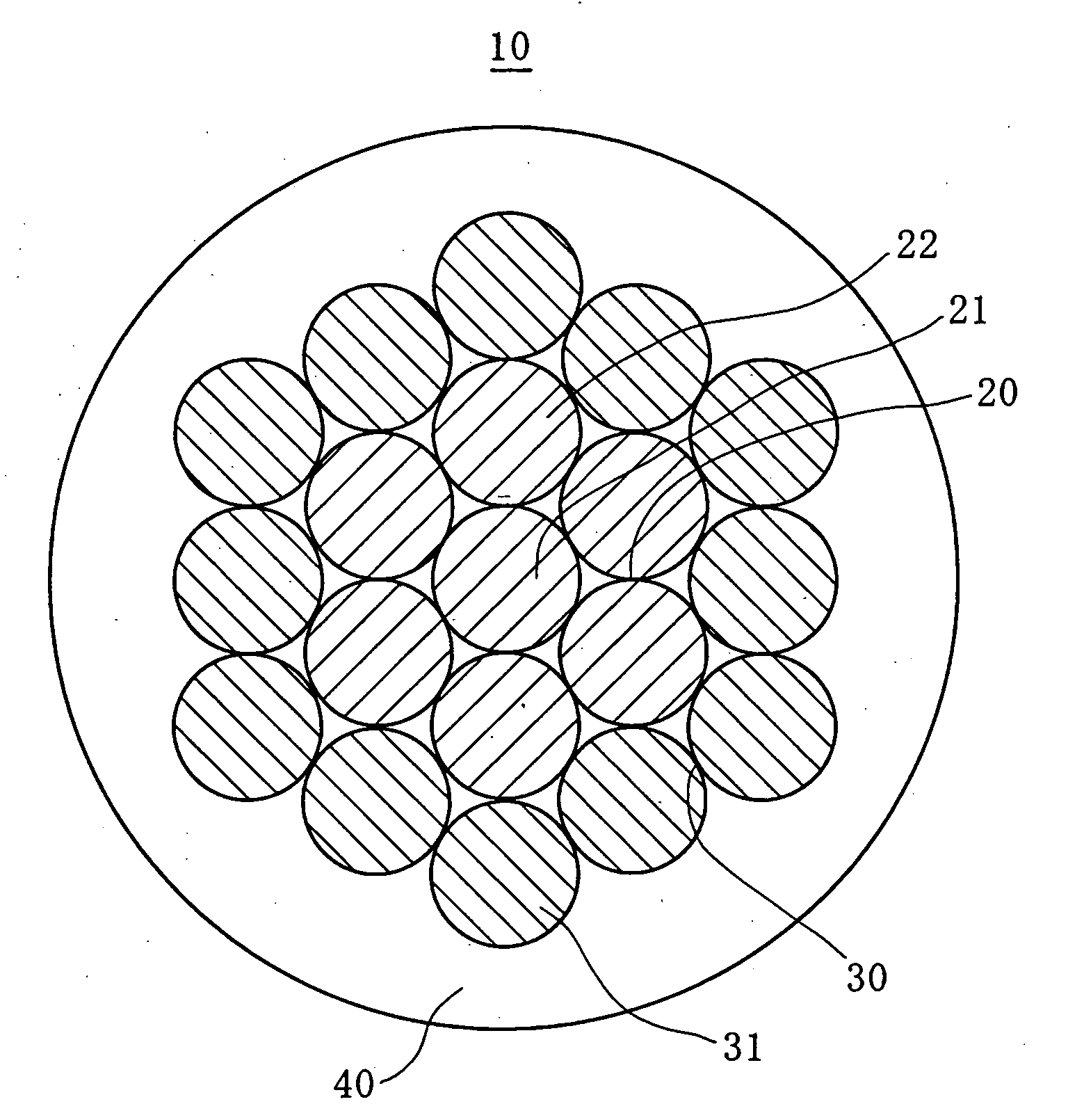
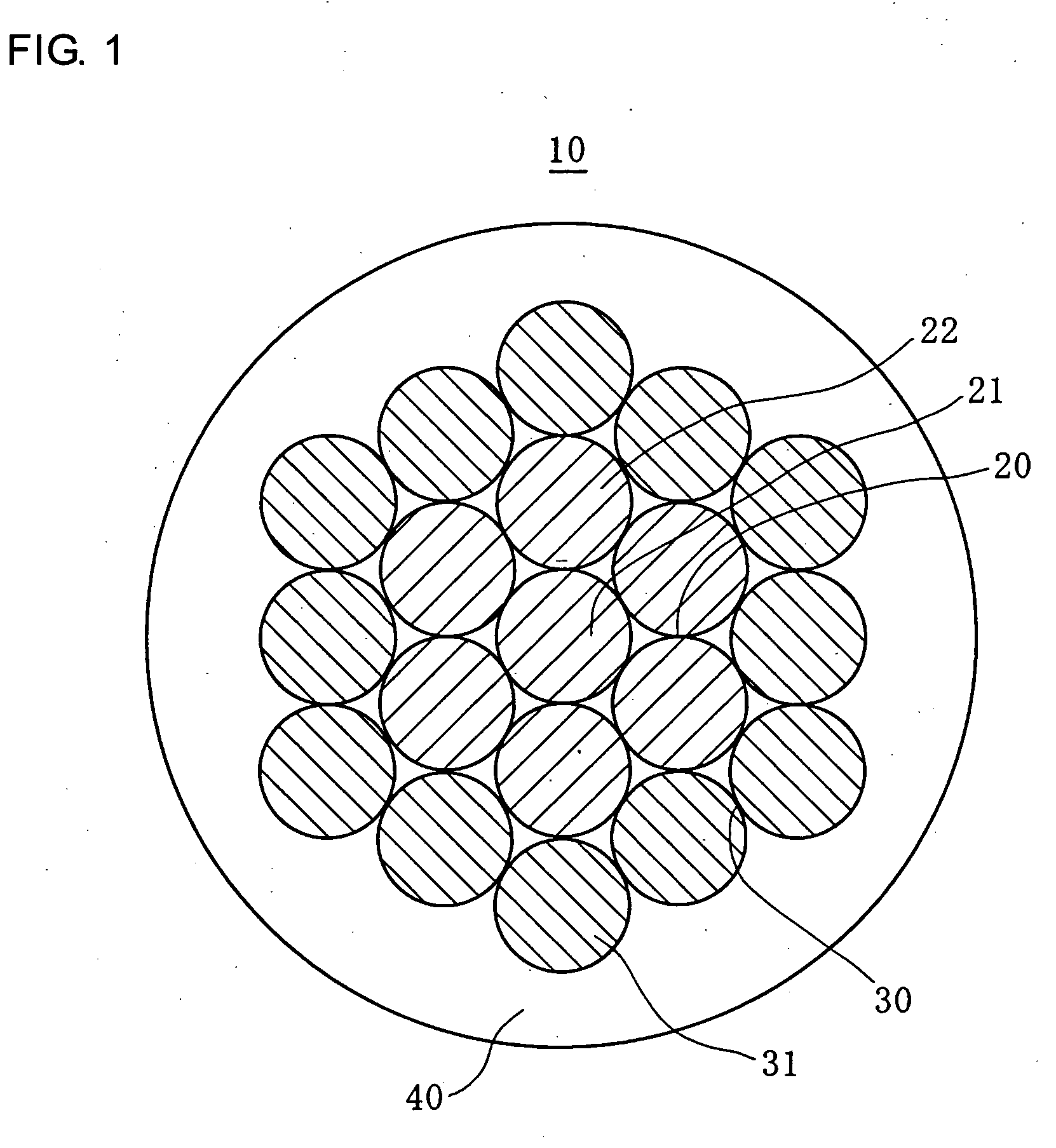
[0071]FIG. 1 schematically shows a cross section of the completed automotive wire 10 according to the present embodiment. In FIG. 1, the reference numeral 20 represents a core wire portion consisting of seven stainless strands in total, the reference numeral 21 represents the central one of the stainless strands, and the reference numeral 22 represents the stainless strands wound around this central stainless strand 21 in single-ply and spiral manner. Further, the reference numeral 30 represents a circumferential wire portion consisting of twelve copper strands in total, and the reference numeral 31 represents the each of the copper strands. Furthermore, the reference numeral 40 represents insulating coating.

(Core Wire Portion)

[0072]Around the single stainless strand 21, the six stainless strands 22, each having a thickness equal thereto...

second embodiment

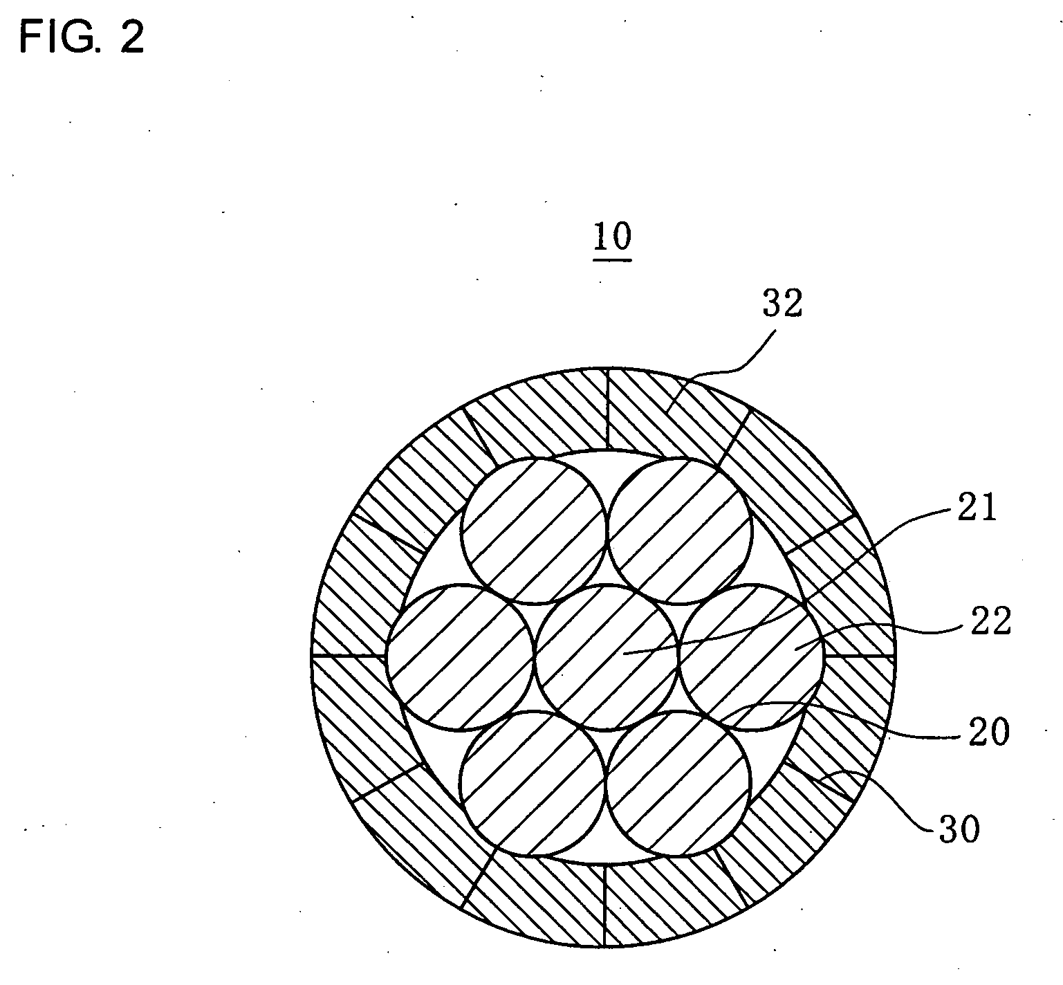
[0094]The present embodiment is implemented by compressing (pressing) copper strands so as to be combined.

[0095]FIG. 2 shows the state of the compressed circumferential wire portion of the electric wire shown in FIG. 1. In this diagram, the reference numeral 32 represents the copper strands, which have been deformed and combined by pressing, i.e., the copper strands constituting the circumferential wire portion.

[0096]The copper strands are made of pure copper having a tensile rupture strength of 230 MPa, meaning that the copper strands are made of a soft material. Therefore, the overall cross section of the twelve copper strands, constituting the circumferential wire portion, is easily formed into a pipe shape due to compression from outside toward the core wire with the use of dies.

[0097]On the other hand, stainless is far harder than (i.e., has Young's modulus higher than that of) pure copper or electrolytic copper. Therefore, unlike the copper strands 32, the stainless strand 21 ...


PUM

PropertyMeasurementUnit
Lengthaaaaaaaaaa
Fractionaaaaaaaaaa
Fractionaaaaaaaaaa

Abstract

An electric wire for an automobile has a core wire section and an outer circumferential wire section. The core wire section is formed by spirally winding six element wires around one element wire, where each element wire is made of stainless steel having elongation of 30% or more and tensile strength of 920 MPa or higher and the element wires have the same diameter in the range of 0.127 mm±10%. The circumferential wire section is formed by spirally winding twelve element wires around the core wire section, where the twelve element wires are wound close to each other in a single layer, each element wire is made of copper having tensile strength of 220 MPa or higher, and the element wires have the same diameter in the range of 0.127 mm±10%. The wire is light, small, strong and has good bending characteristics.

Description

BACKGROUND OF THE INVENTION[0001]1. Field of the Invention[0002]The present invention relates to automotive wires, and, in particular, relates to an automotive wire structured to have a core wire portion consisting of stainless strands and a circumferential wire portion consisting of copper strands.[0003]2. Description of the Related Art[0004]An electric wire for internal wiring (wire harness), used to provide, for example, electric connection of electrical equipment in an automobile, is required not only to have a small diameter, a low electric resistance, a favorable high corrosion resistance, and a good contact with a terminal, but also to exhibit excellent mechanical properties, i.e., a sufficient tensile strength and a favorable bending property. To meet these requirements, various inventions are made. For example, the invention disclosed in JP 09-147361A not only provides a multi-core wire by binding together numerous stainless thin wires each having a favorable corrosion resi...

Claims


Application Information

Patent Timeline
IPC IPC(8): H01B3/44H01B5/08
CPCH01B7/0009H01B5/104
Inventor YOSHIMOTO, JUNKAMEI, SHINJI
Owner SUMITOMO WIRING SYST LTD
Why Eureka
Try Eureka