Apparatus and method for fluorescent imaging

a fluorescent imaging and apparatus technology, applied in the field of apparatus and fluorescent imaging apparatus, can solve the problems of complex electronics, high voltage, and inability to meet the needs of endoscopy, and achieve the effect of increasing the specificity of diagnosis

Inactive Publication Date: 2009-10-29
STORZ ENDOSKOP PROD GMBH
View PDF11 Cites 28 Cited by
  • Summary
  • Abstract
  • Description
  • Claims
  • Application Information

AI Technical Summary

Benefits of technology

[0016]The fluorescence excitation beam may be continuously modulated, and the first image sensor may be a solid state detector that can be powered by phase-sensitive means, while data provided by the first image sensor contain pixel-by-pixel phase information on the fluorescent beam. According to the invention, an endoscopically usable apparatus for fluorescent imaging is provided, which is economical and easy to operate. Continuous modulation of the fluorescence excitation beam may be achieved with relatively simple electronic means, and phase-sensitive solid state sensors are of simple construction, easy to operate, and available at moderate cost. With a corresponding modulation frequency, time delays that lie in the range of the lifetime of frequent fluorescent material may be demonstrated simply and securely. By means of pixel-triggered collection and evaluation of the phase information, it becomes possible to generate an image that depicts locally triggered fluorescence lifetime information. As a result, FLIM, for instance, may be made available for many diagnostic applications in clinical practice.
[0053]In another preferred embodiment of the invention, a stereo image may be synthesized from the 3D data. Such a stereo image may be depicted with an appropriate display device, which displays different images for both of an observer's eyes, and it provides the observer with a lifelike spatial impression of the observed area. This is particularly desirable in endoscopic operations to give the operator improved intuitive control of the instruments he or she operates.

Problems solved by technology

A GOI requires a stable mechanical mounting, complex electronics, high voltages and is not suited for an endoscope during an endoscopic procedure.
This model requires a very high instrumental complexity and is therefore not suited for routine clinical applications.

Method used


Image

  • Apparatus and method for fluorescent imaging
  • Apparatus and method for fluorescent imaging
  • Apparatus and method for fluorescent imaging

Examples


Embodiment Construction

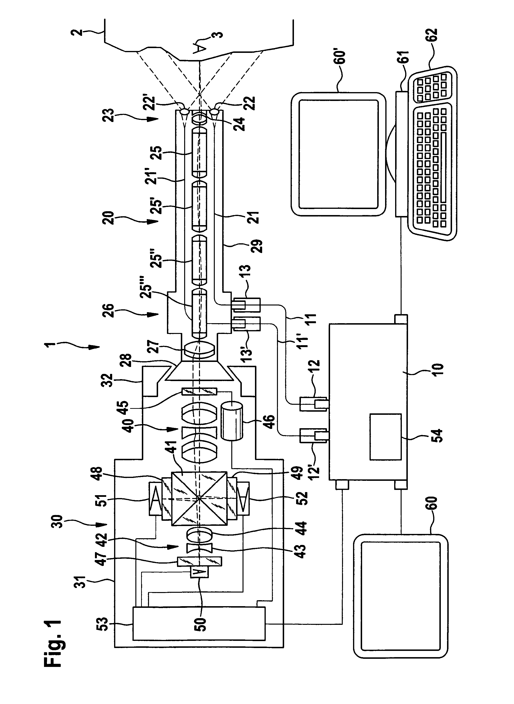
[0067]According to FIG. 1, an inventive apparatus 1 includes light source 10. In the illustrated preferred embodiment the light source is configured to generate a fluorescence excitation beam, modulated continuously, for instance in sinus shape, and a white light illumination.

[0068]For retransmitting both types of beam, light-conducting cables 11, 11′ are provided respectively, and may be connected by connections 12, 12′ with light source 10 and by connections 13, 13′ with endoscope 20. In a corresponding coupling or, for instance, in using a super continuum laser, both types of beams also may be retransmitted by a single light conductor. The light source may also be integrated into the endoscope.

[0069]The fluorescence excitation beam and the white light are conducted to object end 23 (the distal end, at a distance from the observer) of endoscope 20 by means of endoscope light conductors 21, 21′. Enlarging lenses 22, 22′ are positioned to serve to uniformly distribute the illuminati...


PUM

PropertyMeasurementUnit
lengthaaaaaaaaaa
wavelength rangeaaaaaaaaaa
frequencyaaaaaaaaaa

Abstract

An apparatus and method for fluorescent imaging. The apparatus includes a light-generating means for generating at least one modulated fluorescence excitation beam, a light retransmitting means for retransmitting the fluorescence excitation beam onto an area that is to be examined, a light-imaging means for imaging a fluorescent beam from the area to be examined onto a first image sensor, a control and evaluation means for controlling the light-generating means to power the first image sensor and for evaluating the data supplied by the first image sensor to generate a fluorescent image, where the fluorescent excitation beam may be continuously modulated, the first image sensor is a solid state detector that may be powered phase-sensitively, and the data supplied by the first image sensor contain pixel by pixel phase information on the fluorescent beam.

Description

CROSS-REFERENCE TO RELATED APPLICATIONS[0001]The present application claims priority of German Patent application No. 10 2008 018 637.6-51 filed on Apr. 11, 2008 and of European patent application No. 09004957 filed on Apr. 3, 2009.FIELD OF THE INVENTION[0002]The present invention relates to an apparatus and method for fluorescent imaging.BACKGROUND OF THE INVENTION[0003]Apparatuses and methods for fluorescent imaging are known in the art. For instance, WO97 / 11636 discloses an apparatus for diagnosis by means of a reaction caused by a photo-sensitizer or by auto-fluorescence in biological tissue, in which a lighting system for generating a fluorescence excitation light is provided as well as a light-supply unit for illuminating a tissue area that is to be examined with the fluorescent stimulating light. Light coming from the tissue area can be absorbed by an endoscope lens and can be projected in a proximal image plane in which, for instance, the image-absorbing unit can be situated...

Claims


Application Information

Patent Timeline
Patent Type & Authority Applications(United States)
IPC IPC(8): G01N21/64
CPCA61B1/00096H04N13/0275A61B1/0638A61B5/0071A61B5/0073A61B5/0084A61B2562/0242G01N21/4795G01N21/6408G01N21/6456G01N2021/1787G01N2021/6484G02B23/2446G02B23/2484A61B1/043H04N13/275A61B1/00194A61B1/0655
Inventor KRATTIGER, BEAT
Owner STORZ ENDOSKOP PROD GMBH
Why Eureka
Try Eureka