Electric power steering apparatus

Inactive Publication Date: 2009-10-29
NSK LTD
View PDF4 Cites 25 Cited by
  • Summary
  • Abstract
  • Description
  • Claims
  • Application Information

AI Technical Summary

Benefits of technology

[0029]According to an electric power steering apparatus of the invention, the fixing base, which is structured as a composing element of the electric motor, can be used not only to fix the control unit (ECU) but also to cover the connecting portion between the bus bars and control unit. This structure not only can prevent electromagnetic noises generated in the connecting portion from having ill influences on electric parts provided outside the connecting portion but also can prevent a foreign object from touching the connecting portion to thereby cause short-circuiting. As a result of this, since there is eliminated the need for separate provision of a cover member for covering the connecting portion, the number of parts and the number of assembling steps can be reduced, thereby being able to reduce the manufacturing cost of the electric power steering apparatus. Also, since the space of the electric power steering apparatus can be saved, the freedom of the mounting layout of the electric power steering apparatus onto a vehicle can be enhanced.
[0030]Also, owing to employment of a structure in which the fixing base includes a bus bar recessed portion and the opening of the bus bar recessed portion is closed by a control unit which is fixed to the fixing bas

Problems solved by technology

However, in such conventional connecting structure, in some cases, the harness is difficult to mount because of the layout of the vehicle and also there is a fear that extended wiri

Method used


Image

  • Electric power steering apparatus
  • Electric power steering apparatus
  • Electric power steering apparatus

Examples


Example

First Embodiment

[0075]Now, description will be given below of a first embodiment according to the invention with reference to FIGS. 1 to 4.

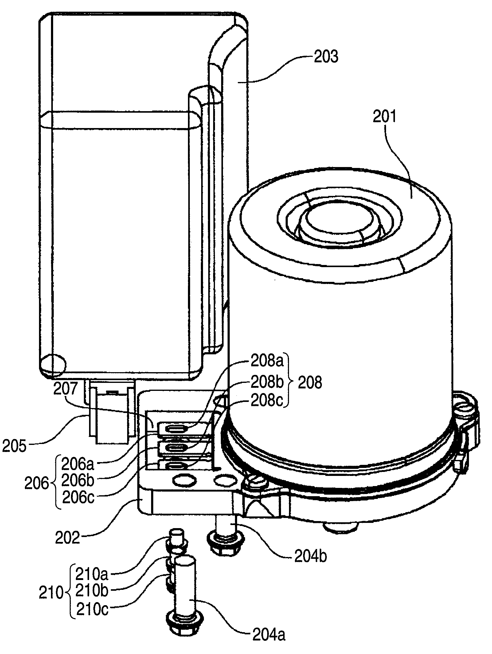
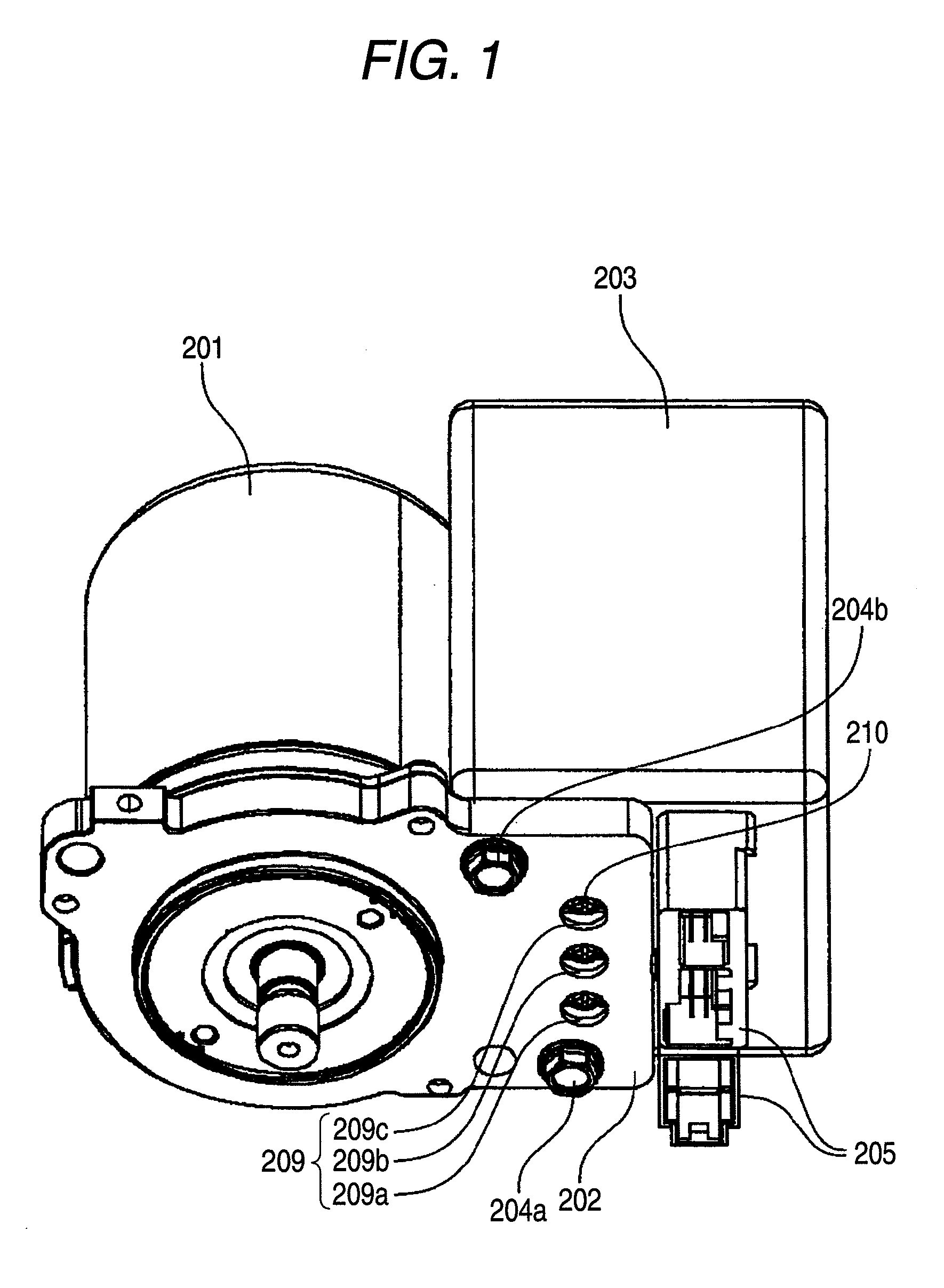
[0076]FIG. 1 is a perspective view of a mounting structure for mounting the electric motor and control unit (ECU) of an electric power steering apparatus according to an embodiment of the invention. In FIG. 1, an electric motor 201 for steering assistance includes a fixing base 202 formed by extending a motor flange which is an element of the composing parts of the electric motor 201. To the fixing base 202, there is fixed a control unit (ECU) 203 for controlling the drive of the electric motor 201 through fixing bolts 204a, 204b. That is, according to the present mounting structure, the electric motor 201 and ECU 203 are disposed adjacent to each other. The ECU 203 is connected to other electric parts such as a power source and various sensors through harnesses (not shown) to be connected to connectors 205 which are provided in the bottom portio...

Example

Second Embodiment

[0085]Now, description will be given below of a second embodiment according to the invention with reference to the accompanying drawings. Specifically, FIG. 6 is a side view of an electric power steering apparatus according to the present invention, FIG. 7 is a bottom view of the electric power steering apparatus shown in FIG. 6, FIG. 8 is a perspective view of an electric motor and a fixing base, FIG. 9 is a perspective view of the fixing base and bus bars when they are viewed from above, FIG. 10 is a perspective view of the fixing base and bus bars when they are viewed from laterally, FIG. 11 is a side view of a bus bar, FIG. 12 is a perspective view of a controller, FIG. 13 is a perspective view of a connecting terminal when it is viewed from ahead, FIG. 14 is an internal structure view of the connecting terminal, FIG. 15 is an internal structure view of the connecting terminal, showing a state in which nuts are mounted, and FIG. 16 is a perspective view of a pro...


PUM


Abstract

An electric power steering apparatus according to the invention includes an electric motor to be connected to a control unit through bus bars respectively projected from the inside of the electric motor and is structured such that the control unit controls the drive of the electric motor to thereby assist the steering of a vehicle. The control unit is fixed to a fixing base which is structured as a composing element of the electric motor, and the fixing base covers the connecting portion between the bus bars and control unit.

Description

TECHNICAL FIELD[0001]The present invention relates to an electric power steering apparatus using an electric motor as a source for generating steering assisting torque and, more specifically, the invention relates to an electric power steering apparatus which is improved not only in a mounting structure for an electric motor and a control unit (ECU) disposed adjacent to the electric motor for controlling the drive of the electric motor, but also in a connecting structure for connecting together an electric motor for applying steering assisting torque to the steering system of a vehicle and a controller for controlling the drive of the electric motor.RELATED ART[0002]In an electric power steering (EPS) apparatus which is carried on a vehicle or the like, an electric motor is driven according to steering torque applied thereto through steering wheels, and the rotation of the electric motor is transmitted through a reduction mechanism to a steering mechanism to thereby assist the steer...

Claims


Application Information

Patent Timeline
IPC IPC(8): H02K11/00H02K11/02
CPCB62D5/0406H02K11/0073H02K7/116H02K5/225H02K11/33
Inventor IMAMURA, YOUSUKEMAEDA, MASAHIROOHNISHI, KOJIYAMAMOTO, TAKESHIEBUCHI, TOMOAKI
Owner NSK LTD
Why Eureka
Try Eureka