System and method for proximity detection

a proximity detection and proximity detection technology, applied in the field of proximity detection systems and methods, can solve the problems of not being able to set up traditional operator protection systems, industrial machines may be necessarily large and powerful, and machines that have injured or killed people while being operated, so as to maintain a safe distance from the machine

Active Publication Date: 2009-10-29
ALLIANCE COAL LLC
View PDF11 Cites 67 Cited by
  • Summary
  • Abstract
  • Description
  • Claims
  • Application Information

AI Technical Summary

Benefits of technology

[0013]What is needed is a system that can determine the location of the operator with respect to the machine and, if necessary, shut the machine down without requiring any structure in the environment. Advantageously, with such a system, the operator will learn to maintain a safe distance from the machine to be efficient in their job.

Problems solved by technology

Industrial machines may be necessarily large and powerful.
Such machines have injured or killed people while being operated.
With respect to the environment, it is may not be possible to set up traditional operator protection systems, such as light fences or guard rails, because the environment is generally unstructured (e.g., mining machines create the environment as they operate).
Further, such environments are often noisy, dusty and wet.
A transducer, speaker or microphone that is exposed to such an environment is not likely to survive or function properly.
For example, sonar and laser time-of-flight sensors exposed to such an environment will become dirty and non-operational very quickly.
Further, such sensors have difficulty distinguishing between a people and other structural components in the environment, such as the wall of the mining space.
With respect to radio time-of-flight sensors, such as radar, while the components may be more durable in the environment the relatively short distances (e.g., two feet to 50 feet) between the operator and the machine make such sensors impractical and unreliable.
Further, the requirement of a relatively large radio dish or directional radio antenna is impractical.
However, this system is limited to a substantially circular safety perimeter around the machine, so there is no ability to arbitrarily define a safety perimeter because there is no way to determine an exact location of the operator with respect to the machine.
This becomes a nuisance because it prevents the operator from operating in areas that are safe and effective because of the lack of geometric control of the safety perimeter.

Method used


Image

  • System and method for proximity detection
  • System and method for proximity detection
  • System and method for proximity detection

Examples


Embodiment Construction

[0040]For the purpose of this document, “intrinsically safe” shall be as defined by the U.S. Department of Labor, Mine Safety and Health Administration (MSHA).

[0041]Further, for the purpose of this document, the various microcontrollers described herein are understood to execute software or program instructions included in or accessible by the microcontrollers in a tangible storage medium, such as random access memory (RAM), read only memory (ROM), Electrically Erasable Programmable Read-Only Memory (EEPROM), flash memory, or the equivalent.

A. System

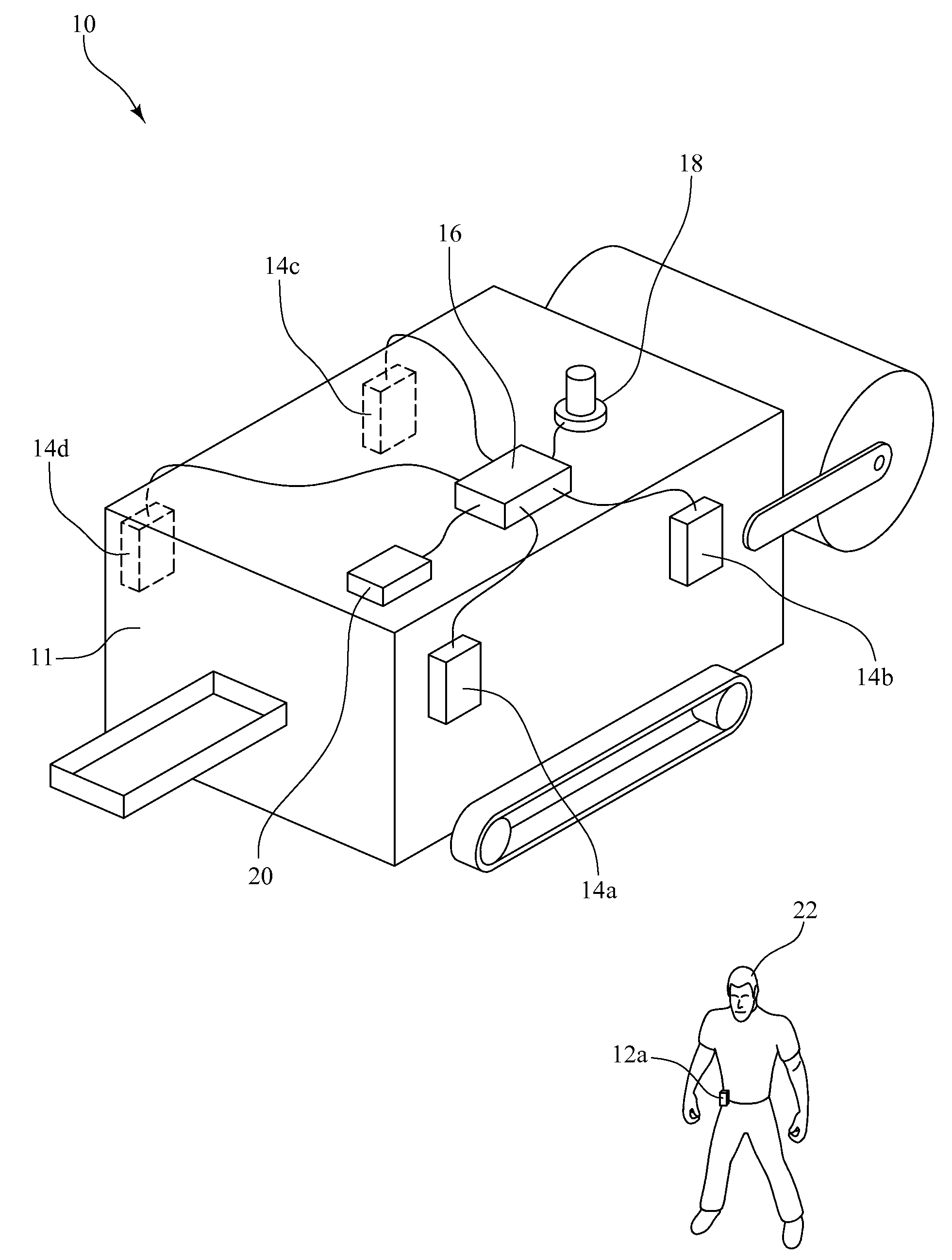
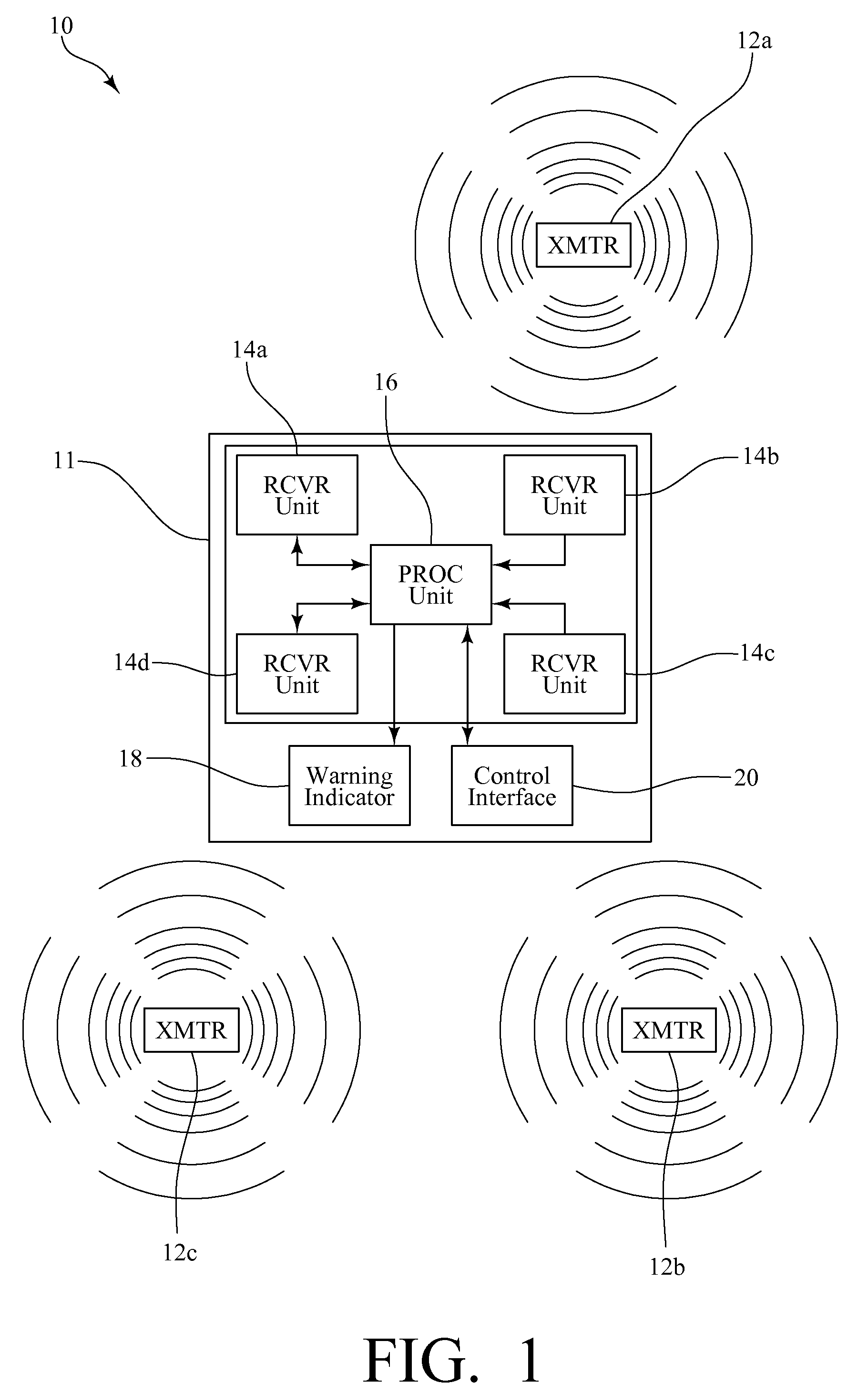
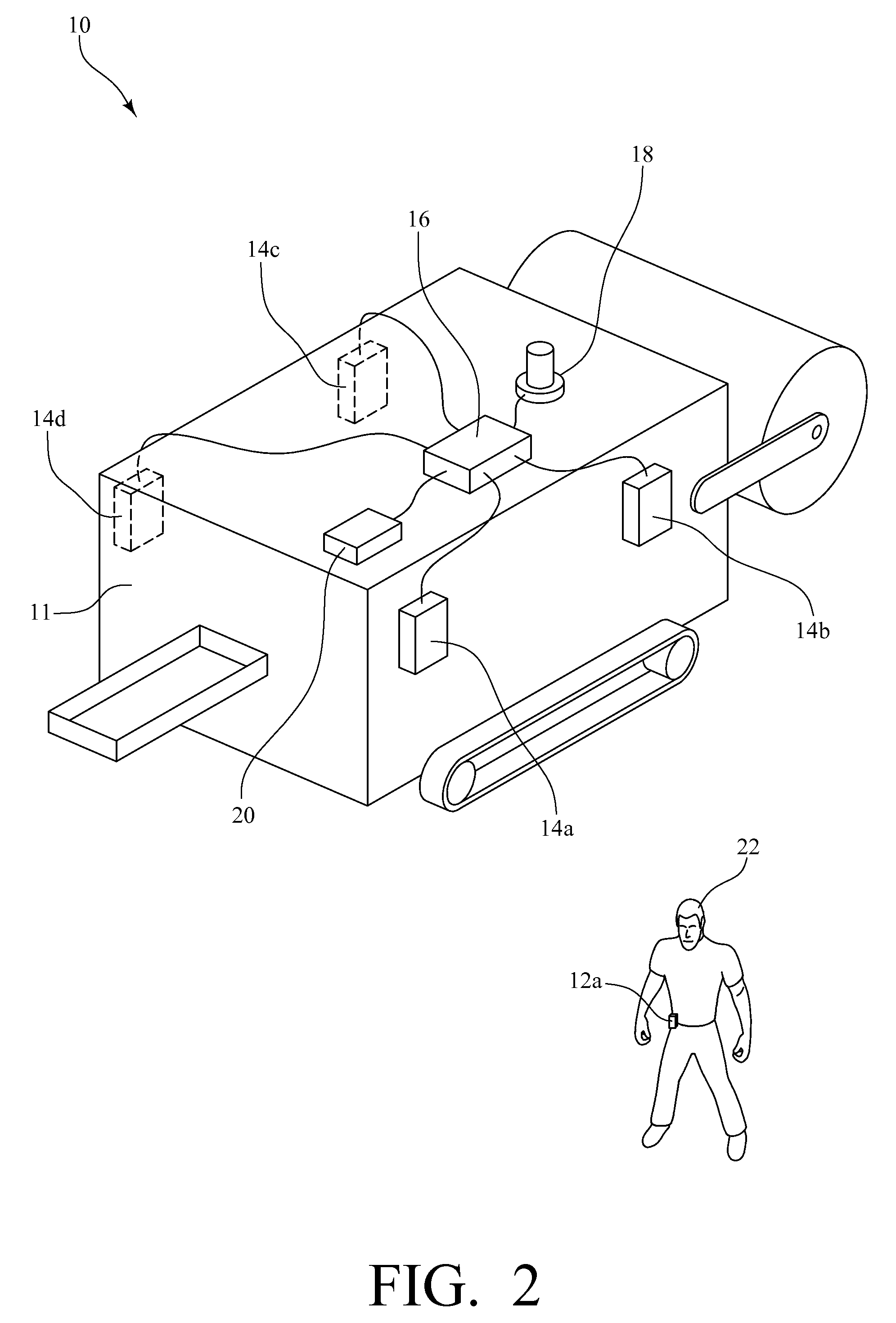
[0042]FIG. 1 and FIG. 2 show an exemplary system 10 for detecting the proximity of a person 22 to a machine 11, including: at least a first transmitter unit 12a, a plurality of receiver units 14a-14d, a processing unit 16, and a warning indicator or device 18. The plurality of receiver units 14a-14d and the processing unit 16 comprise a receiver system. The machine 11 includes a control interface 20 for receiving commands to control oper...


PUM


Abstract

A system and method for detecting a proximity of a person to a machine includes a first transmitter unit carried by the person, a plurality of receiver units located on the machine at know locations, and a processing unit including data defining a first boundary around the machine. The first transmitter unit transmits a magnetic proximity signal having a predetermined signal strength and a predetermined signal frequency. Each of the plurality of receiver units is for determining a received signal strength of the received magnetic proximity signal. The processing unit: determines a location of the first transmitter unit relative to the machine based on the received signal strength of the magnetic proximity signal and the known location of the plurality of receiver units; and outputs a proximity warning signal if the location of the transmitter relative to the machine is within the first boundary around the machine.

Description

CROSS-REFERENCE TO RELATED APPLICATIONS[0001]This application claims the benefit of U.S. Provisional Patent Application No. 61 / 048,735, filed Apr. 29, 2008, and U.S. Provisional Patent Application No. 61 / 081,564, filed Jul. 17, 2008, the entire disclosures of which are incorporated herein by reference.STATEMENT REGARDING FEDERALLY SPONSORED RESEARCH OR DEVELOPMENT[0002]Not applicable.[0003]Not applicable.INCORPORATION-BY-REFERENCE OF MATERIAL SUBMITTED ON A COMPACT DISC[0004]Not applicable.BACKGROUND OF THE INVENTION[0005]1. Field of the Invention[0006]The present invention relates to a system and method for the detection of a transmitter unit in the proximity of a receiver system. More specifically, the present invention relates to a system that detects the proximity of a person carrying the transmitter to a dangerous machine configured with the receiver system, and determines if that person is close enough to be in danger.[0007]2. Description of Prior Art[0008]Industrial machines ...

Claims


Application Information

Patent Timeline
Patent Type & Authority Applications(United States)
IPC IPC(8): G08B21/00
CPCG08B21/0213G08B21/0225F16P3/147G08B21/0261F16P3/145G08B21/0233
Inventor PRYOR, ARICWATSON, MARKCIHOLAS, MIKE E.BENNETT, JUSTIN E.BLAYLOCK, PAUL R.ELPERS, CHRISTOPHER J.BUCHANAN, EVAN M.GANDER, CHRISTOPHERDEBAILLIE, TIMOTHY M.
Owner ALLIANCE COAL LLC
Why Eureka
Try Eureka