System and Method For Lens Shading Correction Of An Image Sensor Using Splines

a technology of image sensor and lens, applied in the field of lens shading correction of image sensor, can solve the problems of difficulty in uniformly projecting an image, lens shading correction, and asymmetric shading effects, and achieve the effect of accurate shading correction

Active Publication Date: 2009-10-29
OMNIVISION TECH INC
View PDF5 Cites 54 Cited by
  • Summary
  • Abstract
  • Description
  • Claims
  • Application Information

AI Technical Summary

Problems solved by technology

One issue that arises in the operation of image sensors is the need to perform lens shading correction.
However, various imperfections in the optical assembly create a shading effect.
More generally there will be a two-dimensional variation in shading across the array of pixels caused by the optical elements in the optical assembly and the difficulties in uniformly projecting an image across the field of view of the image sensor.
Additionally, in the most general case shading effects may be asymmetric.
Uncorrected shading effects can result in undesirable variations in intensity across an image that may be discernable to an end user.
Both of these conventional solutions have significant drawbacks.
However, these fundamental assumptions underlying the symmetric method are not valid for many types of packaged image sensors unless special attention is taken in the design of the optical components.
Studies by the inventors indicate that the symmetric method often generates poor correction results for a variety of packaged image sensors.
However, a drawback of this approach is that it is difficult to accurately correct the entire image.
In particular, investigations by the inventors indicate that a single quadratic polynomial that properly corrects the center of the image will often not adequately correct the corner regions of the image sensor.

Method used


Image

  • System and Method For Lens Shading Correction Of An Image Sensor Using Splines
  • System and Method For Lens Shading Correction Of An Image Sensor Using Splines
  • System and Method For Lens Shading Correction Of An Image Sensor Using Splines

Examples


Embodiment Construction

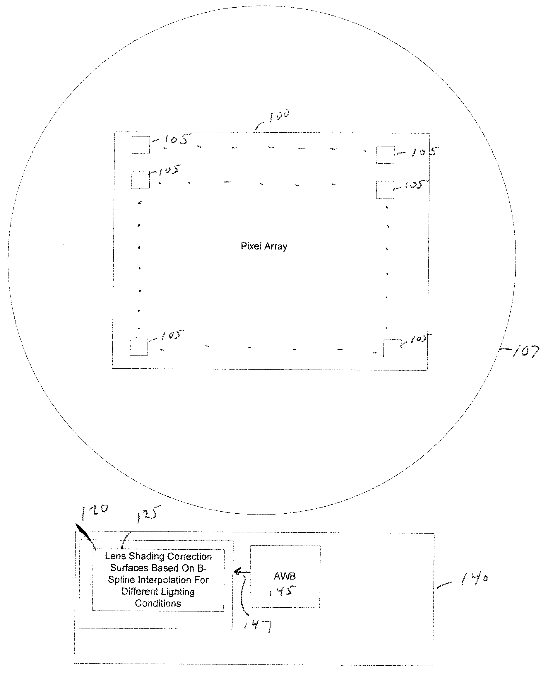
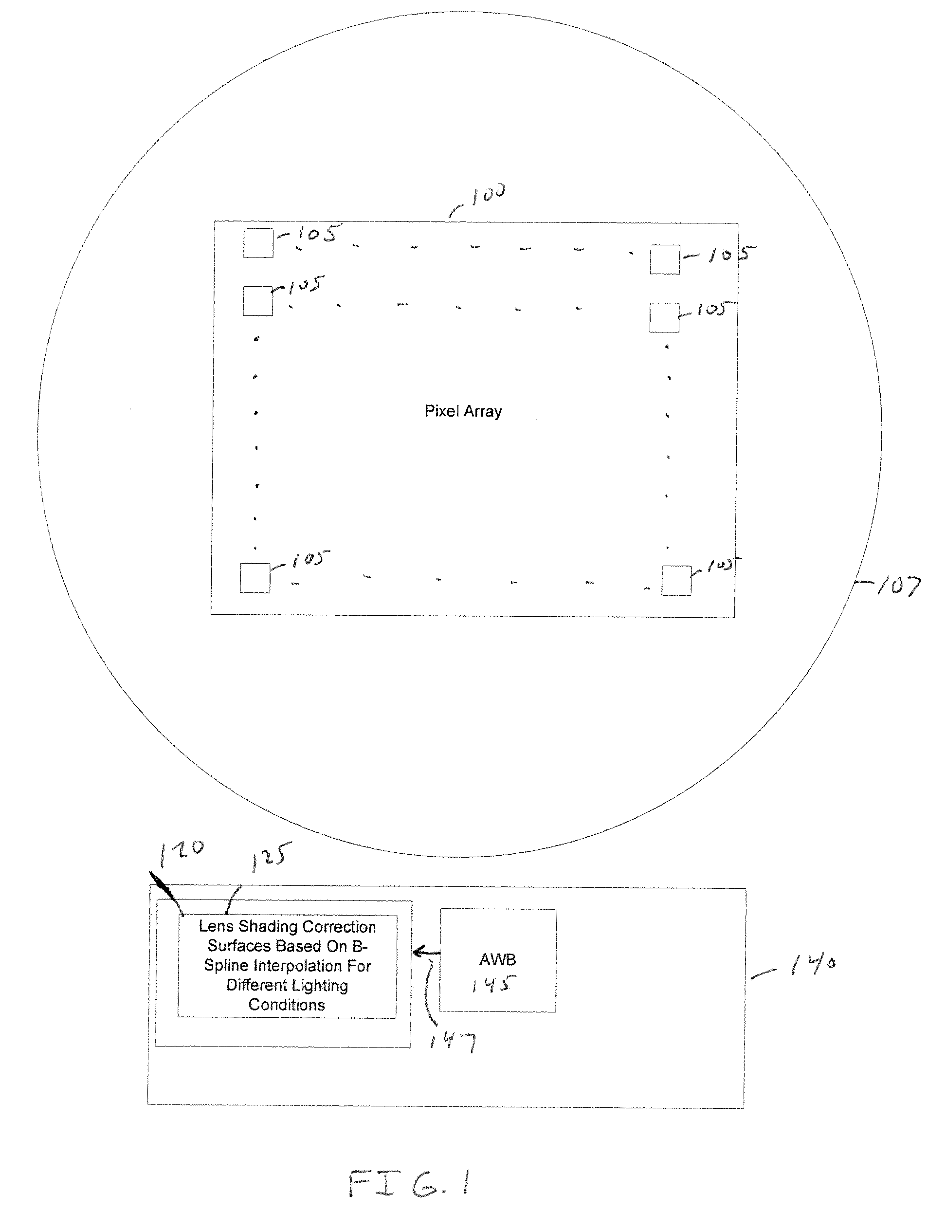
[0018]FIG. 1 is a block diagram illustrating an image sensing system having an image sensor 100 with an array of photo-sensitive pixels 105. The photo-sensitive pixels are arranged in rows (in an x-dimension) and columns (in a y-dimension). As an illustrative example image sensor 100 may be implemented as a complementary metal oxide semiconductor (CMOS) image sensor. An image processor 140 receives captured images from image sensor 100 and processes the captured images.

[0019]In a packaged optical module, light is focused onto each pixel 105 of image sensor 100 via optical components such as a lens 107 (illustrated as a circle for illustrative purposes). However, more generally a packaged optical module may also include other optical components known in the art, such as a color filter array (CFA) micro-lens array to direct light to each pixel and also define different pixel colors. The combined optical response of all optical components in the packaged optical module results in a len...


PUM


Abstract

An image sensing system provides for accurate lens shading correction even when there is significant lens shading asymmetry and non-uniformity. A two-dimensional B-spline technique is used to determine lens shading correction surfaces. The number of zones is selected to achieve accurate correction of center, edge, and corner regions of an image. Separate lens shading correction surfaces are calculated for a set of standard illuminants to permit lens shading correction to be adapted based on the illuminant used to capture the image.

Description

FIELD OF THE INVENTION[0001]The present invention is generally related to techniques to correct for lens shading in image sensors. More particularly, the present invention is directed to using two-dimensional B-spline curve fitting to perform a lens shading correction.BACKGROUND OF THE INVENTION[0002]One issue that arises in the operation of image sensors is the need to perform lens shading correction. An image sensor typically has a two-dimensional array of photo-sensitive pixels. An optical assembly may include a lens and a micro-lens array to focus light onto individual pixels. However, various imperfections in the optical assembly create a shading effect. One common shading effect is that that the image is brighter in the center and decreases in brightness at the edges of the pixel array. More generally there will be a two-dimensional variation in shading across the array of pixels caused by the optical elements in the optical assembly and the difficulties in uniformly projectin...

Claims


Application Information

Patent Timeline
Patent Type & Authority Applications(United States)
IPC IPC(8): H04N5/235
CPCH01L27/14625H04N5/3572H01L27/14627H04N25/61
Inventor WANG, XIAOYONGSHAN, JIZHANGWU, DONGHUI
Owner OMNIVISION TECH INC
Why Eureka
Try Eureka