
Method and apparatus for stripping holes in a metal substrate

a metal substrate and stripping technology, applied in the direction of cleaning using liquids, instruments, manufacturing tools, etc., can solve the problems of holes less effective or useless for their intended purpose, wear of normal protective coatings applied to such components, and substantial difficulty in the removal process

Active Publication Date: 2009-10-29
OPTOMEC INC
View PDF11 Cites 29 Cited by
  • Summary
  • Abstract
  • Description
  • Claims
  • Application Information

AI Technical Summary

Benefits of technology

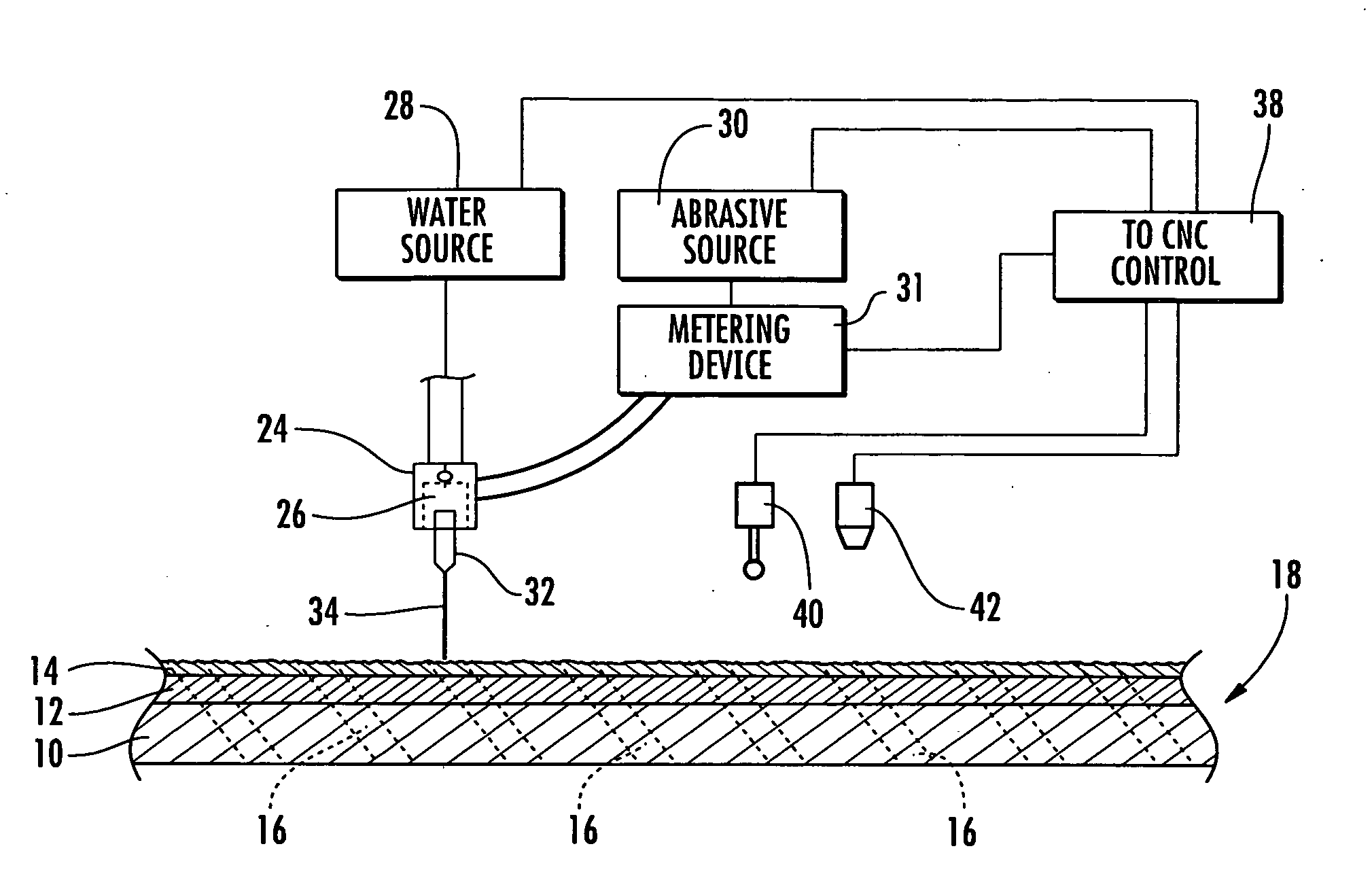
[0022]The method may also include the step of causing a reverse flow of low pressure liquid, such as water, outwardly though the holes in an opposite direction the high pressure water jet, and this reverse flow may be carried out while the high pressure water jet is being directed into a hole. If the substrate includes a cavity in fluid communication with the hole, the method may include the step of filling the cavity with water while the hole is being stripped by the high pressure water jet to thereby protect the walls of the cavity.

Problems solved by technology

Because turbine components are subjected during normal use to extremely high temperatures as well as significant temperature variations, such components become somewhat distorted, twisted or leans during use, and the normal protective coatings applied to such components become worn.
This removal process is substantially more difficult in situations where the metal substrate also has a coating over an exposed surface of the substrate, and the holes are covered in whole or in part by the coating.
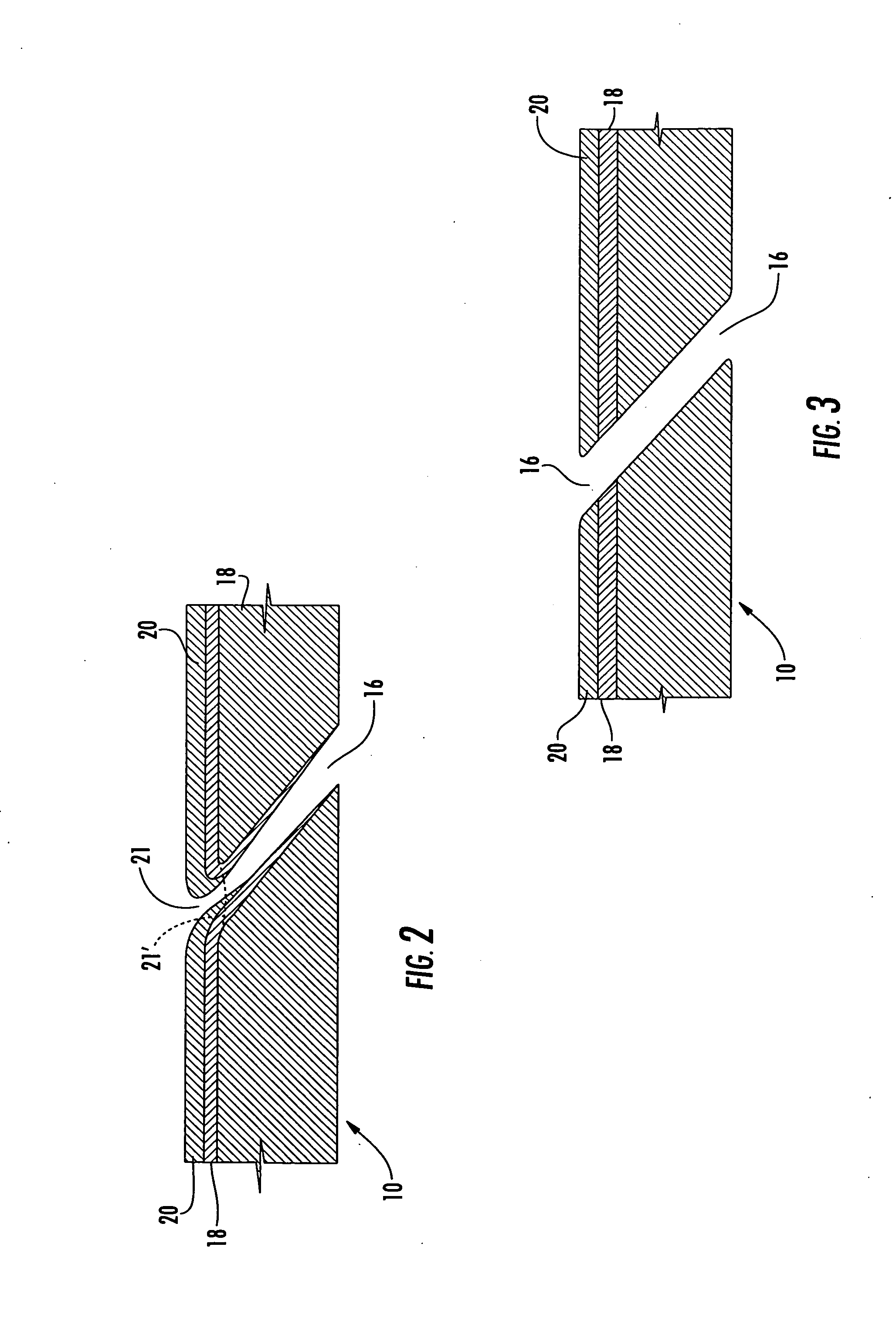
It will apparent, however, that if these coatings are applied over the surface of a turbine component that is formed with the holes as described above, the coating or coatings either partially fill or completely fill the holes which will significantly obstruct the flow of cooling gas through the holes and thereby render the holes less effective or useless for their intended purpose unless the holes are stripped or cleared of most if not all of the coating material within the holes.
When it is recognized that many turbine components have a very large number of holes that must be manually stripped using this known method, it will be apparent that the process of manually stripping all of such holes is very time consuming and labor intensive.

Method used


Image

  • Method and apparatus for stripping holes in a metal substrate
  • Method and apparatus for stripping holes in a metal substrate
  • Method and apparatus for stripping holes in a metal substrate

Examples


Embodiment Construction

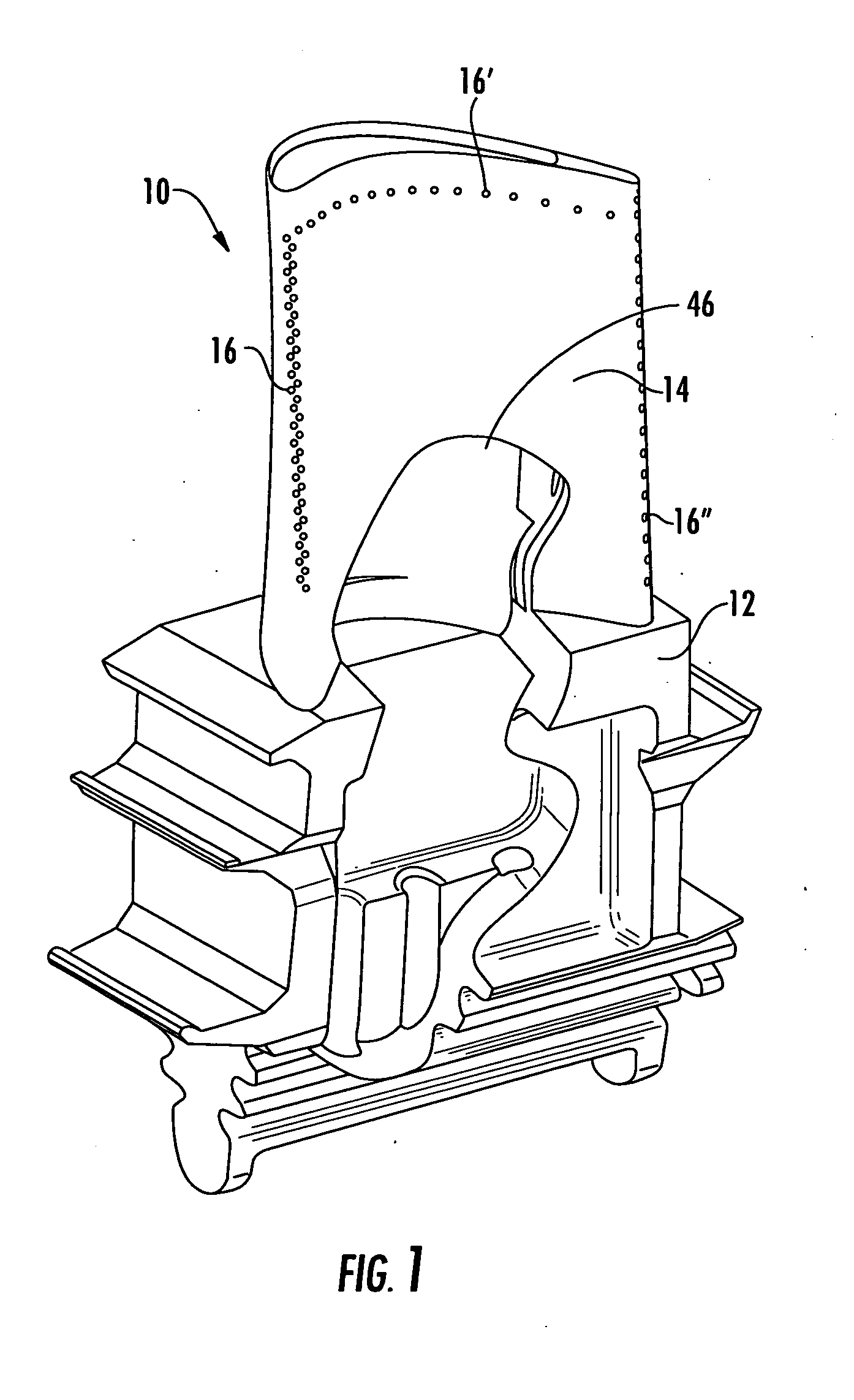
[0026]FIG. 1 is a drawing of a metal substrate, which in this case is a typical turbine component, namely a turbine blade, which can be repaired utilizing the method and apparatus of the present invention, but it will be understood that many other substrates and other turbine components can also be repaired. The turbine component illustrated in FIG. 1 is a conventional turbine blade 10 of the type that is used in a gas turbine engine, and it includes a base portion 12, and a blade portion 14, both of which are formed with a pattern of holes 16 through which a cooling gas is discharged from interior compartments within the blade portion 10 and the base portion 12, one of which is identified by the reference numeral 46 in FIG. 1, to form a thermal barrier film across the exterior surface of the turbine blade 10 as discussed above, and as is well known in the art. The pattern of holes 16 illustrated in FIG. 1 is merely one representative pattern of a large number of different hole patt...


PUM

PropertyMeasurementUnit
Pressureaaaaaaaaaa
Abrasiveaaaaaaaaaa
Distanceaaaaaaaaaa

Abstract

A method and apparatus for stripping foreign matter from holes in a substrate, such as a turbine component, which includes using a scanner to locate the hole and operating a water jet apparatus to direct a water jet or an abrasive water jet into the hole for stripping. A CAD model of the original turbine component may be used in the control system of the water jet apparatus to initially locate the scanner at the general or theoretical location of the hole. A reverse flow of low pressure water may be provided to further clear foreign matter from the hole.

Description

CROSS-REFERENCE TO RELATED APPLICATIONS[0001]This application is entitled to the benefit of, and claims priority to, provisional U.S. Patent Application Ser. No. 61 / 125,847, filed Apr. 29, 2008, and entitled “METHOD AND APPARATUS FOR STRIPPING HOLES IN METAL,” the entirety of which is incorporated herein by reference.BACKGROUND OF THE INVENTION[0002]The present invention relates generally to a method and apparatus for stripping holes of foreign matter to clear the holes, and more particularly to a method and apparatus for stripping holes in a metal substrate having a coating or other foreign matter applied thereto.[0003]One such metal substrate is turbine components. Because turbine components are subjected during normal use to extremely high temperatures as well as significant temperature variations, such components become somewhat distorted, twisted or leans during use, and the normal protective coatings applied to such components become worn. As a result, these components are oft...

Claims


Application Information

Patent Timeline
IPC IPC(8): B24B49/00B24C1/00
CPCB08B3/024B08B9/00B23P2700/06B24C1/04B24C1/083F05D2260/607C23C4/005C23C4/02F01D5/186F01D5/288F01D25/002B24C1/086C23C4/01Y10T83/0443
Inventor MILLER, MITCHELL O.CASKEY, CLYDE W.
Owner OPTOMEC INC
Learn More