
Pulse Area Modulation and High-Efficiency Linear Power Amplifier System Using the Same

a technology of pulse area and power amplifier, applied in the direction of amplifiers, dc amplifiers with modulator-demodulator, amplifiers, etc., can solve the problems of poor efficiency of class ab amplifier, limited capacity and the size of battery cells, and low-power circuits for mobile terminals. , to achieve the effect of reducing harmonic components

Active Publication Date: 2009-11-05
SEOUL NAT UNIV R&DB FOUND
View PDF6 Cites 22 Cited by
  • Summary
  • Abstract
  • Description
  • Claims
  • Application Information

AI Technical Summary

Benefits of technology

[0007]It is, therefore, an object of the present invention to provide a pulse area modulation method and a high-efficiency linear power amplifier system using the same, capable of effectively reducing the harmonic components without having to use a high-Q band pass filter in the linear power amplifier system.
[0008]It is another object of the present invention to provide the pulse area modulation method and the high-efficiency linear power amplifier system using the same, capable of enhancing the efficiency of the linear power amplifier system by reducing the harmonic components in the linear power amplifier system.

Problems solved by technology

Specifically, low-power circuits for the mobile terminals are required because the capacities and the sizes of battery cells have a limitation.
However, the class A or the class AB amplifier has poor efficiency in that they have great power losses.
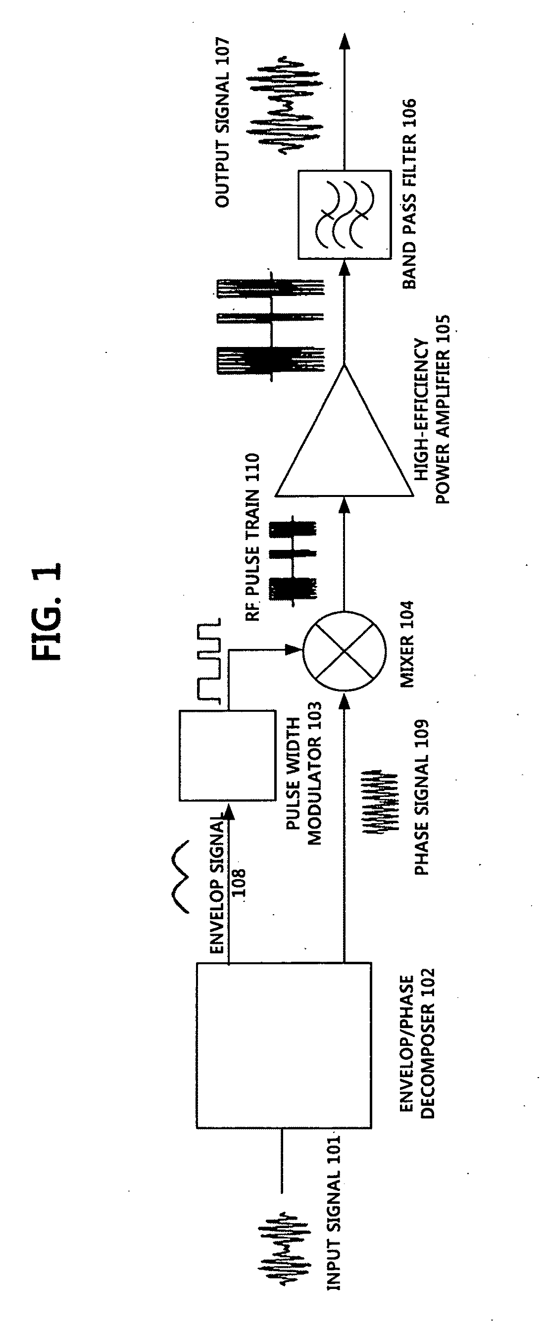
Although the high-efficiency linear power amplifier system has ideally 100% efficiency, the BPF 106 may not eliminate the harmonic components perfectly because the harmonic components are generated adjacent to an inband signal in the frequency domain, resulting in degradation of the linearity, i.e., the efficiency of the linear power amplifier.

Method used


Image

  • Pulse Area Modulation and High-Efficiency Linear Power Amplifier System Using the Same
  • Pulse Area Modulation and High-Efficiency Linear Power Amplifier System Using the Same
  • Pulse Area Modulation and High-Efficiency Linear Power Amplifier System Using the Same

Examples


Embodiment Construction

[0019]To fulfill the above-described objects, the present invention proposes a pulse area modulation (PAM) technique. The efficiency of a power amplifier can be enhanced by using the PAM by reducing harmonic components. Herein, the term “PAM” (pulse area modulation), which is newly proposed in the specification of the present invention, should be distinguished from the well-known term “PAM” (pulse amplitude modulation).

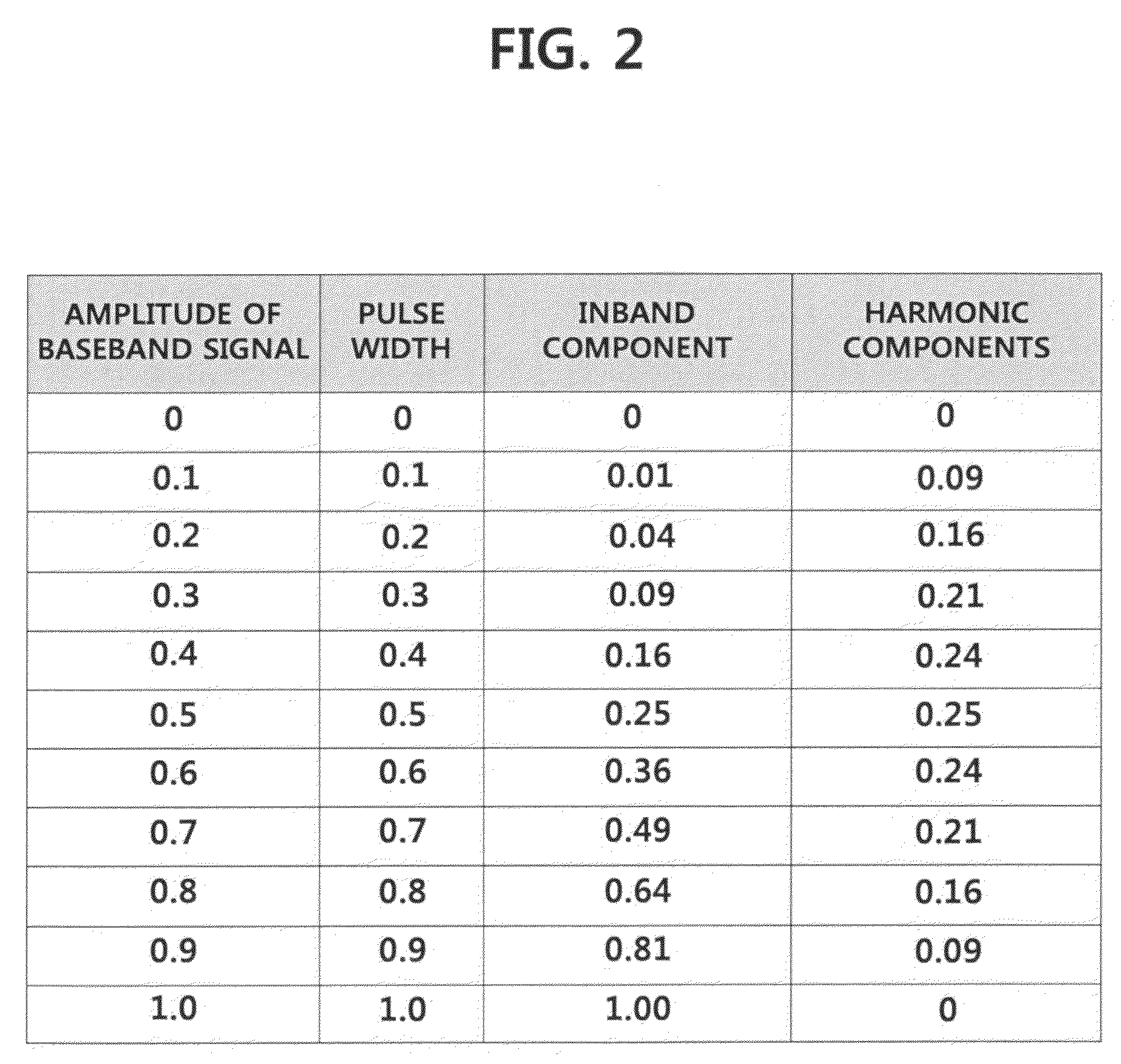
[0020]The PAM is a technique of modulating an input signal such that a modulated pulse has an area, which is proportional to the amplitude of the input signal. Unlike the well-known PWM, whose pulse has a fixed height, the PAM has at least two different pulse heights, which are determined by considering the amplitude of the input signal. Thus, both the width and the height of the modulated pulse vary in the PAM technique as the amplitude of the input signal varies in the time domain, while only pulse width varies in the PWM technique. Though both waveforms have same p...


PUM


Abstract

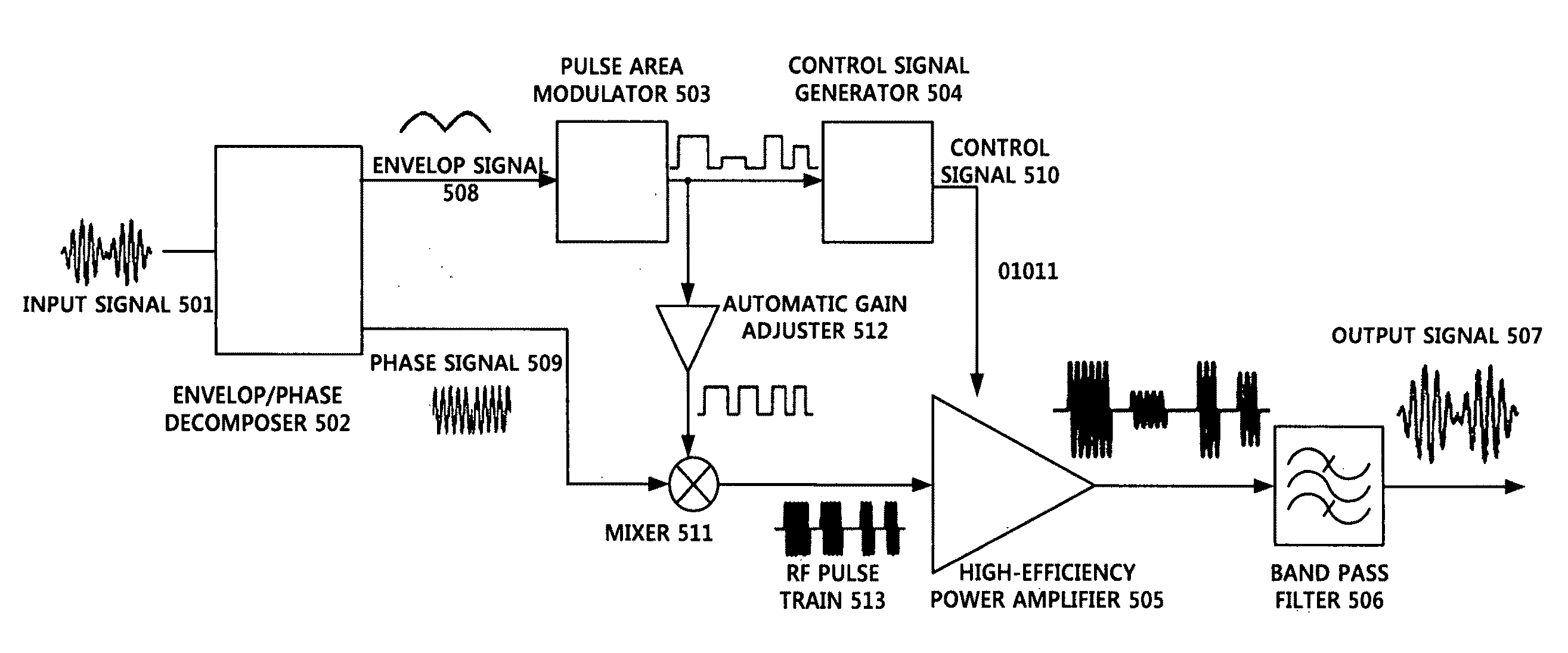
A linear power amplifier system using pulse area modulation includes: an envelop / phase decomposer for decomposing an input signal into an envelop signal and a phase signal; a pulse area modulator for modulating the envelop signal such that an area of the modulated envelop signal is proportional to an amplitude of the envelop signal; a control signal generator for converting the modulated envelop signal into a control signal; an automatic gain adjuster for equalizing pulse height of the modulated envelop signal; a mixer for mixing the phase signal with the output of the automatic gain adjustor to produce a RF pulse train; a power amplifier for amplifying the RF pulse train, to generate an amplified RF pulse train; and a band pass filter for restoring the original input signal from the amplified RF pulse train. The output level of the power amplifier is controlled by the control signal.

Description

FIELD OF THE INVENTION[0001]The present invention relates to pulse area modulation (PAM) and a high-efficiency linear power amplifier system using the same; and, more particularly, to the linear power-amplifier system adopting the PAM capable of reducing harmonic components without having to use a high-Q band pass filter.BACKGROUND OF THE INVENTION[0002]As various mobile communication systems are developed, an efficiency of mobile terminals becomes a very important factor. Specifically, low-power circuits for the mobile terminals are required because the capacities and the sizes of battery cells have a limitation. Among components of the mobile terminals, power amplifiers are dominant power-consumers, so that the efficiency of the mobile terminals adopting, e.g., a CDMA or an OFDM, is at most 20%. The reason why the efficiency of the mobile terminals adopting the CDMA or the OFDM is low is that the envelopes of signals vary. For the purpose of amplifying the signals whose envelopes ...

Claims


Application Information

Patent Timeline
IPC IPC(8): H03F3/38
CPCH03F3/217H03F1/32
Inventor NAM, SANG-WOOKJEON, YOUNG-SANG
Owner SEOUL NAT UNIV R&DB FOUND
Learn More