SiC junction barrier controlled schottky rectifier

a junction barrier and rectifier technology, applied in the field of schottky rectifiers, can solve the problems of considerable leakage current at reverse bias, further lowering of schottky barrier, etc., and achieve the effect of effectively reducing leakage current and improving the problem of large curren

Active Publication Date: 2016-06-14
SHANGHAI HESTIA POWER INC
View PDF8 Cites 15 Cited by
  • Summary
  • Abstract
  • Description
  • Claims
  • Application Information

AI Technical Summary

Benefits of technology

[0008]As such, in the present invention, the junction field-effect regions are disposed at the n-type drift layer, and the p-type doping region surrounds the junction field-effect regions to form the N circular regions and the (N−1) inter-circle regions between every two of the circular regions. Accordingly, when the SiC junction barrier controlled Schottky rectifier operates under a reverse bias, the junction field-effect regions are capable of effectively reducing the leakage current through the circular regions and the inter-circle regions, thereby improving the issue of a large current of a conventional Schottky barrier diode.

Problems solved by technology

However, the Schottky barrier would be further lowered due to the image force induced barrier lowering, which will result in a considerable leakage current at a reverse bias.

Method used


Image

  • SiC junction barrier controlled schottky rectifier
  • SiC junction barrier controlled schottky rectifier
  • SiC junction barrier controlled schottky rectifier

Examples


Embodiment Construction

[0018]The foregoing, as well as additional objects, features and advantages of the invention will be more readily apparent from the following detailed description, which proceeds with reference to the accompanying drawings.

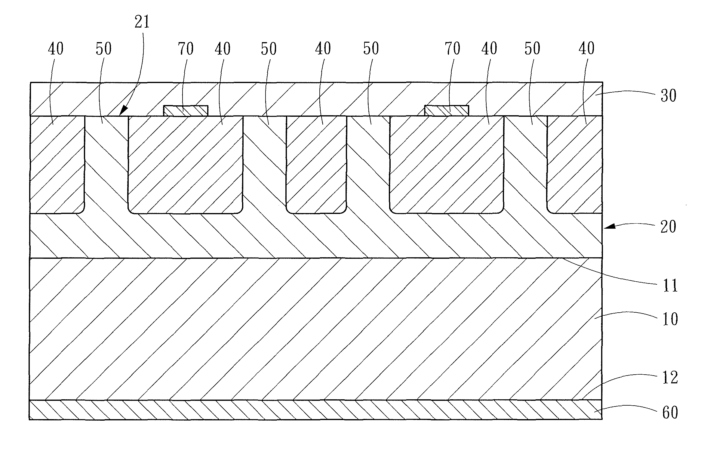
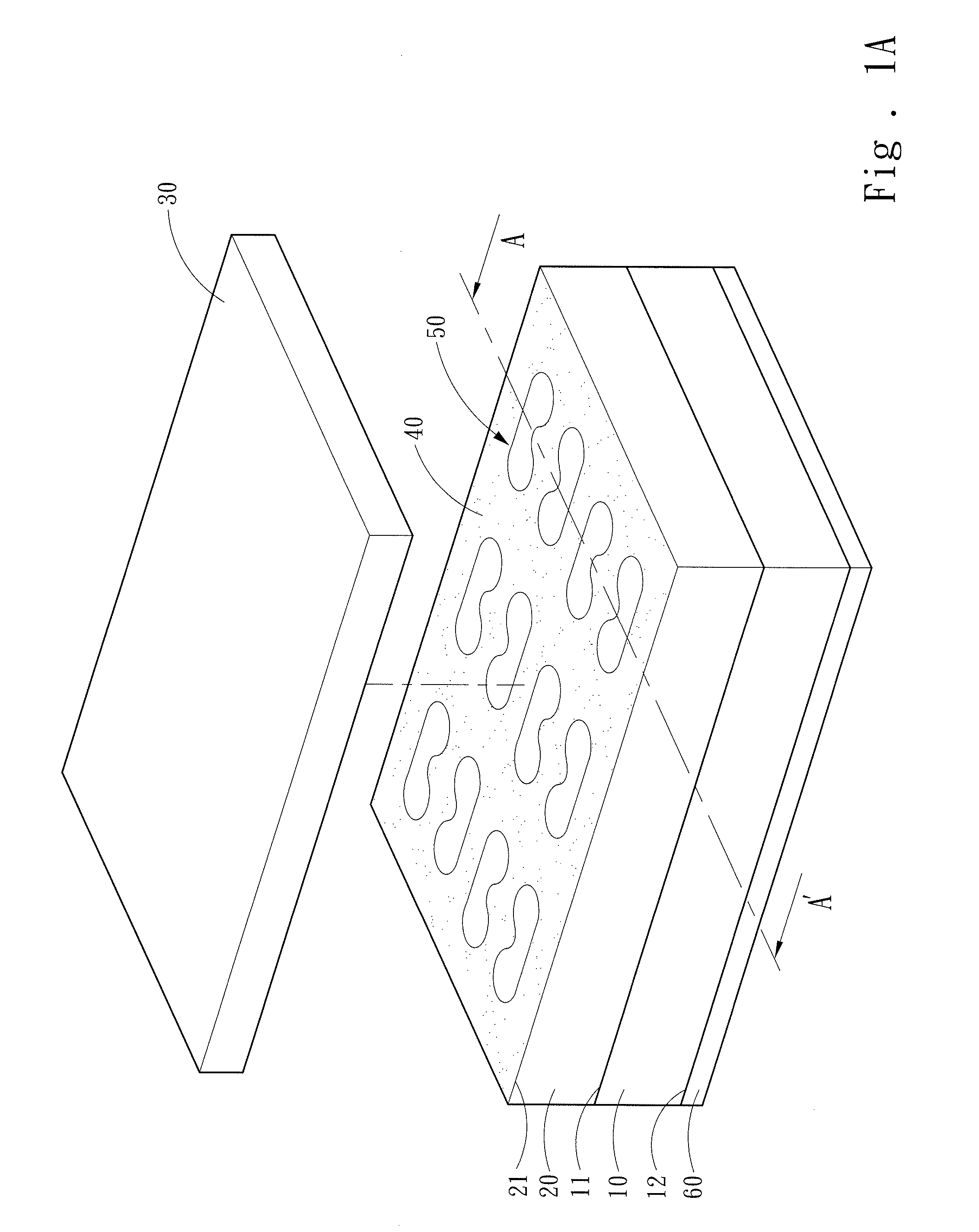
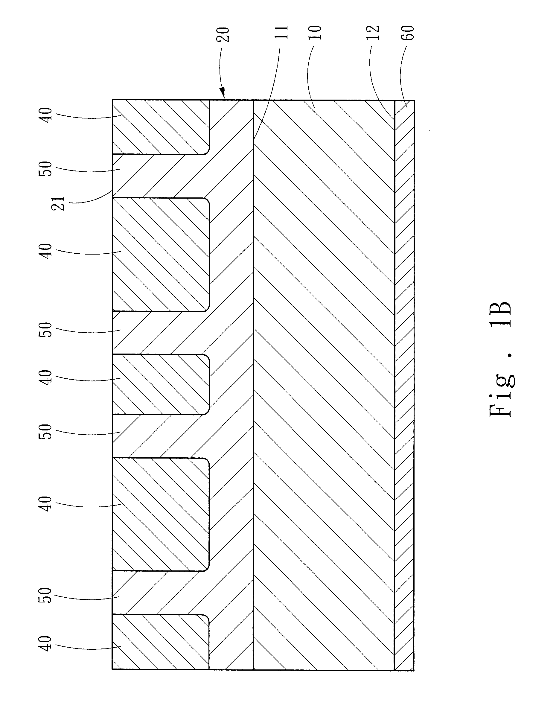
[0019]FIG. 1A shows an exploded diagram of an appearance according to a first embodiment of the present invention. FIG. 1B shows a partial section view of FIG. 1A. FIG. 2 shows a top view of a drift layer according to the first embodiment of the present invention. Referring to FIGS. 1A, 1B and 2, a SiC junction barrier controlled Schottky rectifier includes a SiC substrate 10, a n-type drift layer 20, a p-type doping region 40, a plurality of junction field-effect regions 50, a first metal layer 30 and a second metal layer 60.

[0020]The SiC substrate 10 may be obtained by cutting SiC crystals into a predetermined thickness or growing SiC crystals on any substrate, or may be a commercial SiC substrate 10. Given that a substrate having SiC crystals formed on its surf...


PUM

PropertyMeasurementUnit
resistivityaaaaaaaaaa
thicknessaaaaaaaaaa
blocking voltageaaaaaaaaaa

Abstract

A SiC junction barrier controlled Schottky rectifier includes a SiC substrate, a n-type drift layer, a p-type doping region, a plurality of junction field-effect regions, a first metal layer and a second metal layer. The drift layer is disposed on the SiC substrate. The junction field-effect regions are disposed in the drift layer and are surrounded by the p-type doping region. The first metal layer is disposed on the drift layer. The second metal layer is disposed at one side of the SiC substrate away from the drift layer. Through N circular regions and (N−1) inter-circle regions each connecting two of the circular regions, as well as geometric characteristics of the circular regions and the inter-circle regions, a leakage current of devices is effectively reduced and ruggedness is increased to improve an issue of a large leakage current of a conventional Schottky barrier diode.

Description

FIELD OF THE INVENTION[0001]The present invention relates to a semiconductor device, and particularly to a SiC Schottky rectifier.BACKGROUND OF THE INVENTION[0002]SiC features a wide bandgap, and excellent chemical stability, electrical conductivity and heat conductivity. Power devices are extensively employed in various alternating-current to direct-current (AC / DC) conversion applications, and demand characteristics of low turn-on resistance, low leakage current, high breakdown voltage and fast switching in order to reduce turn-on loss and switching loss generated during operations. As SiC offers a high critical electric field of dielectric breakdown due to its wide bandgap, as well as an intrinsic carrier concentration far lower than doping concentrations in the devices, SiC power devices are suitable for high temperature, high frequency and high power applications.[0003]For example, the U.S. Patent Publication No. US2006 / 0022292 discloses a structure, “Schottky Barrier Diode” (SB...

Claims


Application Information

Patent Timeline
Patent Type & Authority Patents(United States)
IPC IPC(8): H01L29/872H01L29/16H01L29/45H01L29/47
CPCH01L29/872H01L29/1608H01L29/47H01L29/45H01L29/0619H01L29/0688
Inventor YEN, CHENG-TYNGHUNG, CHIEN-CHUNGLEE, CHWAN-YINGLEE, LURNG-SHEHNG
Owner SHANGHAI HESTIA POWER INC
Why Eureka
Try Eureka