Detection of synchronization mark from output of matched filter upstream of viterbi detector

Inactive Publication Date: 2009-11-05
WESTERN DIGITAL TECH INC
View PDF9 Cites 108 Cited by
  • Summary
  • Abstract
  • Description
  • Claims
  • Application Information

AI Technical Summary

Benefits of technology

[0010]Embodiments of the present invention relate to the detection of synchronization marks in data storage and retrieval. According to one embodiment, synchronization marks are detected from the output of a matched filter, upstream of the Viterbi detector. This approach avoids the delay associated with the latency of the Viter

Problems solved by technology

A real densities increase, inter-symbol interference (ISI), transition-dependent noise and non-linear distortions at high densities, and bandwidth limitations at high data rates lead to performance degradation.
In current disk drives with increasing speed and data

Method used


Image

  • Detection of synchronization mark from output of matched filter upstream of viterbi detector
  • Detection of synchronization mark from output of matched filter upstream of viterbi detector
  • Detection of synchronization mark from output of matched filter upstream of viterbi detector

Examples


Embodiment Construction

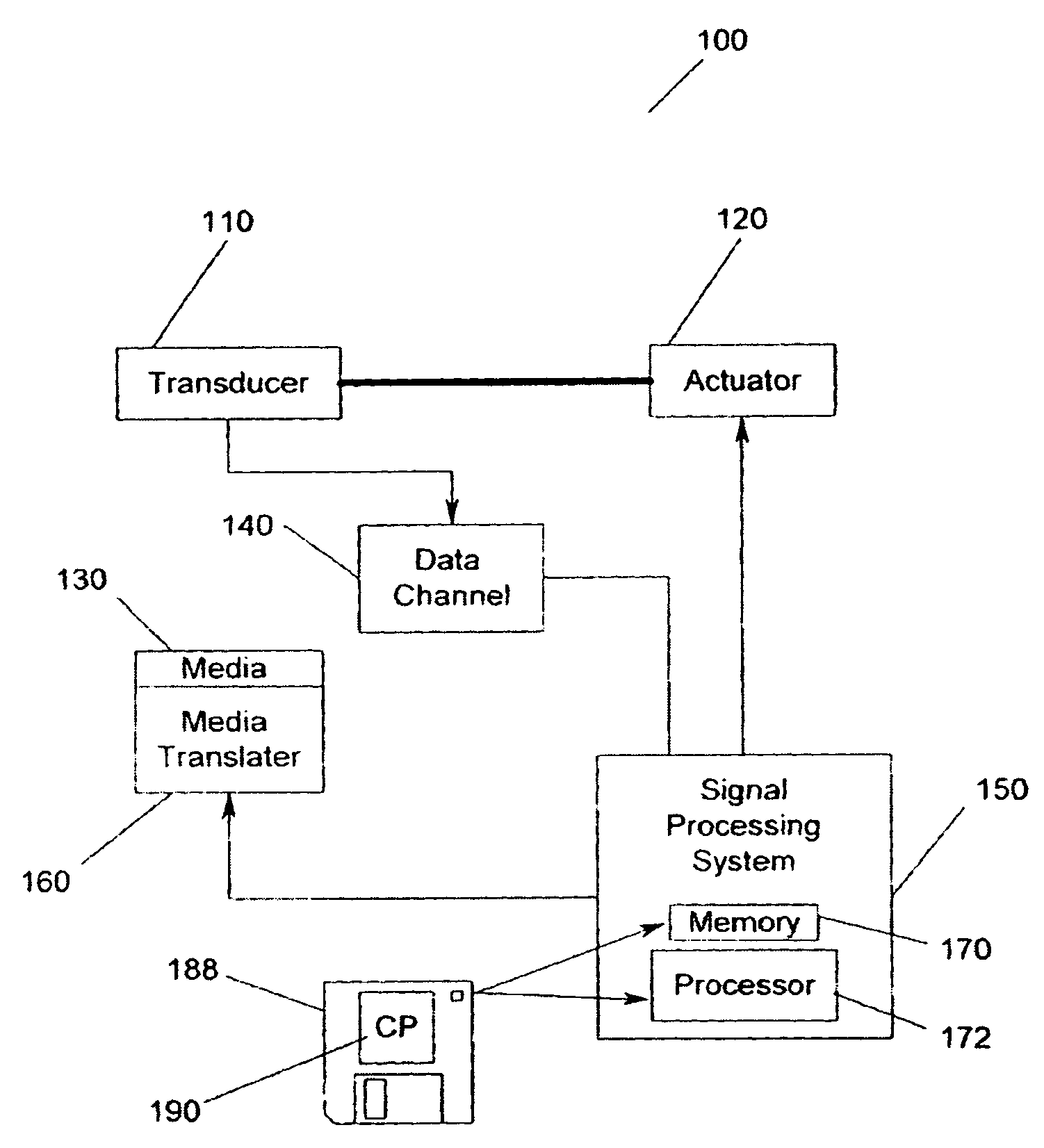
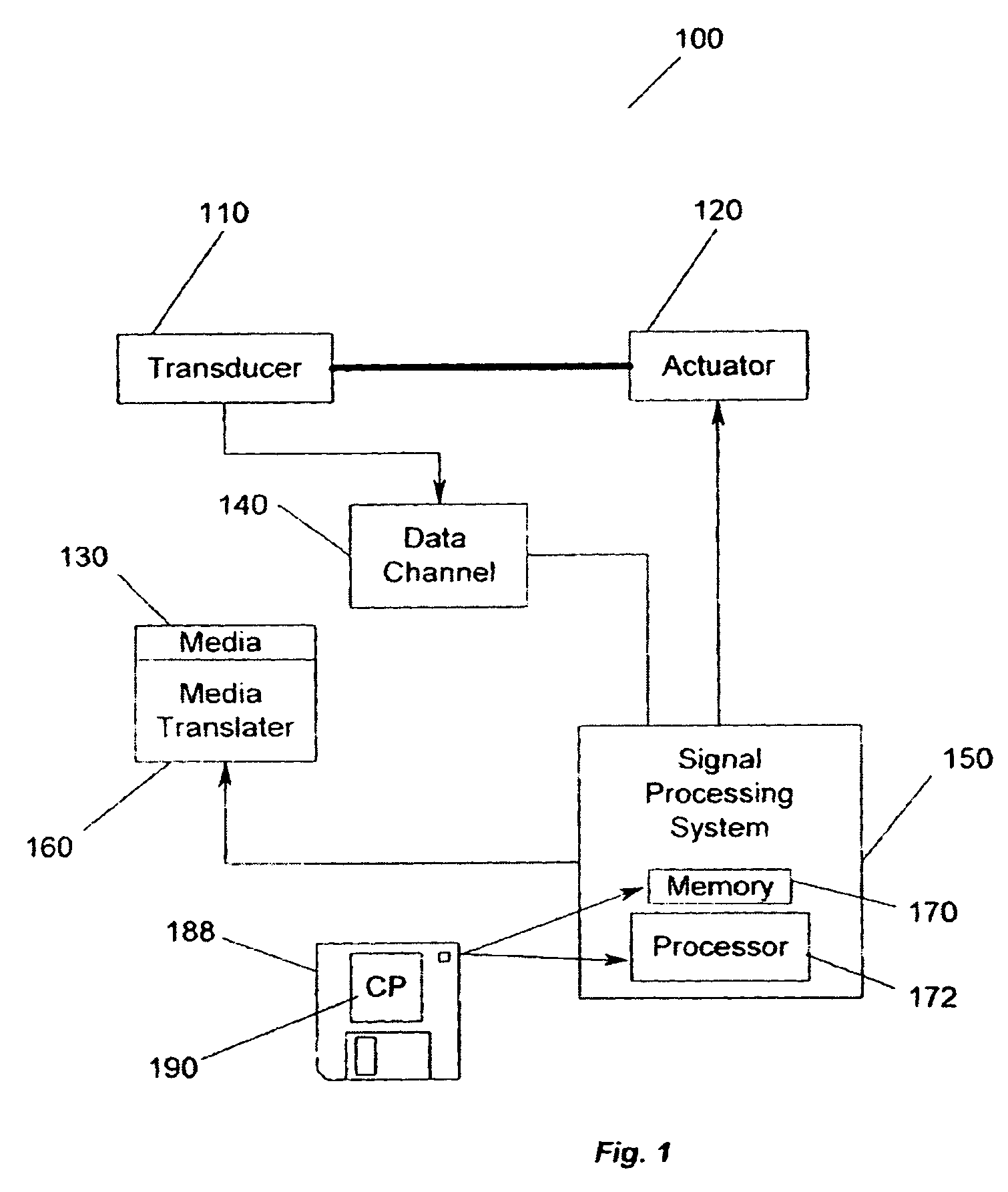
[0030]FIG. 1 illustrates a storage system 100 according to an embodiment of the present invention. In FIG. 1, a transducer 110 is under control of an actuator 120. The actuator 120 controls the position of the transducer 110. The transducer 110 writes and reads data on magnetic media 130. The read / write signals are passed to a data channel 140. A signal processor system 150 controls the actuator 120 and processes the signals of the data channel 140. In addition, a media translator 160 is controlled by the signal processor system 150 to cause the magnetic media 130 to move relative to the transducer 110. Nevertheless, the present invention is not meant to be limited to a particular type of storage system 100 or to the type of media 130 used in the storage system 100.

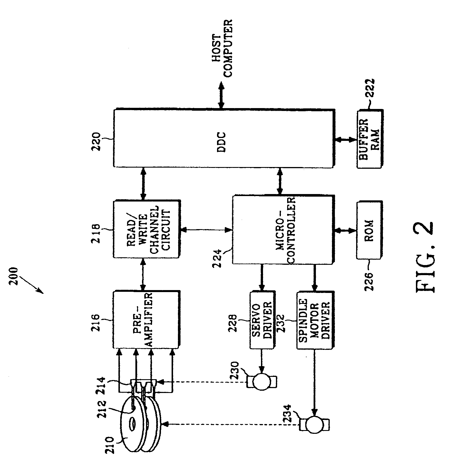
[0031]FIG. 2 is a block diagram of a magnetic disk drive device 200 according to an embodiment of the present invention. In FIG. 2, disks 210 are rotated by a spindle motor 234, and heads 212 are positioned at surfaces of...


PUM


Abstract

Embodiments of the present invention relate to the detection of synchronization marks in data storage and retrieval. According to one embodiment, synchronization marks are detected from the output of a matched filter, upstream of the Viterbi detector. This approach avoids the delay associated with the latency of the Viterbi output, thereby allowing time to align parity framing and to properly start the time-varying trellis. Certain embodiments disclose 34- and 20-bit primary synchronization marks located at the beginning of a data region. Other embodiments disclose 16-, 20-, and 24-bit embedded synchronization marks located within a data region.

Description

BACKGROUND OF THE INVENTION[0001]Recently developed data storage devices, such as magnetic disk drive devices (i.e., hard disk drives), have increased storage capacity and increased data access speed. The magnetic disk drive devices have become widely used as auxiliary memory devices for computer systems. The primary components of a magnetic disk drive device that affect storage capacity and access speed are the magnetic recording head, the recording medium, the servo mechanism, the signal processing technique used in the read / write channel, and the like. A real densities increase, inter-symbol interference (ISI), transition-dependent noise and non-linear distortions at high densities, and bandwidth limitations at high data rates lead to performance degradation. For example, the level of IS between neighboring recorded bits in magnetic recording channels increases with recording density.[0002]The signal processing techniques utilizing PRML (Partial Response Maximum Likelihood) detec...

Claims


Application Information

Patent Timeline
IPC IPC(8): H03D1/00
CPCG11B20/10009G11B20/10027G11B20/10046G11B20/10055G11B20/10212G11B20/10287H03M13/6343G11B20/1217G11B20/14G11B2020/1287G11B2220/2516H03M13/41G11B20/10296
Inventor GALBRAITH, RICHARD LEOHANSON, WELDON MARKOENNING, TRAVIS ROGERTRUAX, TODD CARTER
Owner WESTERN DIGITAL TECH INC
Why Eureka
Try Eureka