
System in Package High Power Highly Efficient Diode Lamp

a diode lamp, high-efficiency technology, applied in semiconductor devices, lighting and heating apparatus, instruments, etc., can solve the problems of low inability to increase the light intensity of diode lamps, and low lighting efficiency of led lamps. achieve the effect of high power and high efficiency

Inactive Publication Date: 2009-11-12
ENRAYTEK OPTOELECTRONICS
View PDF17 Cites 14 Cited by
  • Summary
  • Abstract
  • Description
  • Claims
  • Application Information

AI Technical Summary

Benefits of technology

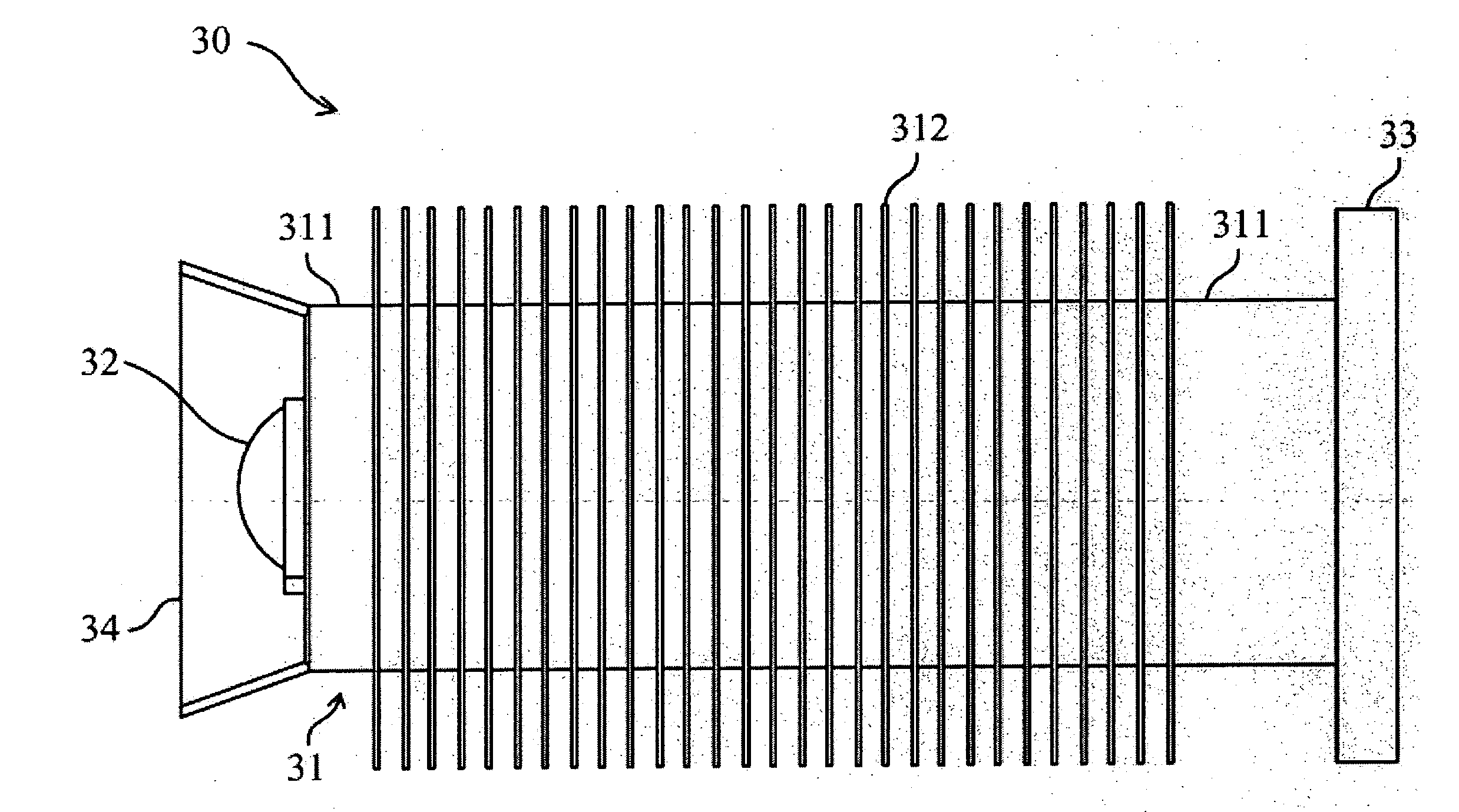
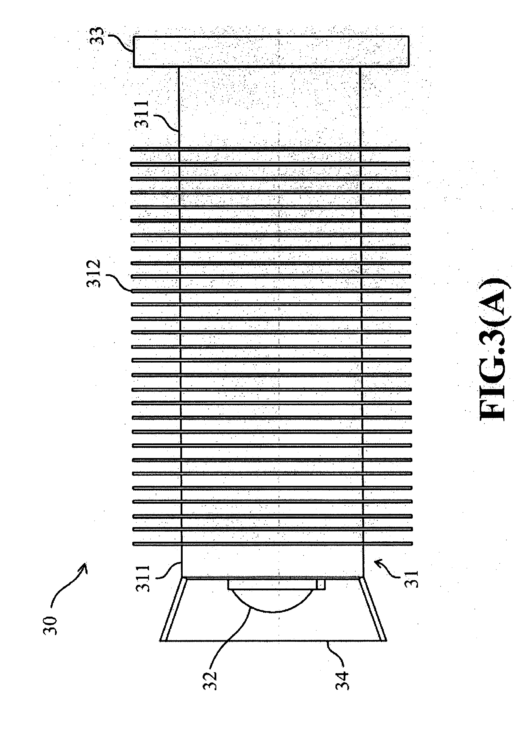
[0008]The first main purpose of this invention is to provide a system-in-package, high power, and highly efficient diode lamp. One preferred embodiment, according to this invention, is a diode lamp which includes a heat-conducting / heat-dissipating module, a LED light module, an optical module, and a control circuit module. The heat-conducting / heat-dissipating module includes a heat-conducting device and at least one heat-dissipating fin. The LED light module is mounted on a flat portion of the heat-conducting device and jointed to the flat portion smoothly and closely. The optical module is used for focusing light emitted by the LED light module. The control circuit module is used for controlling the LED light module. When the diode lamp is electrically connected to a power supply, the control circuit module selectively controls the LED light module to emit light. Heat, generated during the operation of the LED light module, is conducted from the flat portion of the heat-conducting device to the at least one heat-dissipating fin and is dissipated by the at least one heat-dissipating fin.
[0009]Because the heat-conducting / heat-dissipating module is integrated with the LED light module in the diode lamp, according to this invention, heat generated by the LED light module can be immediately dissipated into surrounding air by the heat-dissipating fins. Thus, the heat-dissipating efficiency of the diode lamp is greatly raised. Therefore, compared with prior arts, the diode lamp, according to this invention, is more adaptive to lighting devices that requires high power and highly efficient diode lamps.
[0011]The third main purpose of this invention is to provide a diode lamp that can be extensively integrated to present lighting devices. The diode lamps in the aforementioned embodiments can further include a casing. The casing can be designed to be adapted to present cylindrical or rectangular batteries. Therefore, it is easy to integrate the diode lamp, according to this invention, to current power sources.

Problems solved by technology

However, after being turned on for a while, the temperature of high power LEDs in prior arts will be too high.
The lighting efficiency of LEDs is thus decreased, and their light intensity can not be further increased.
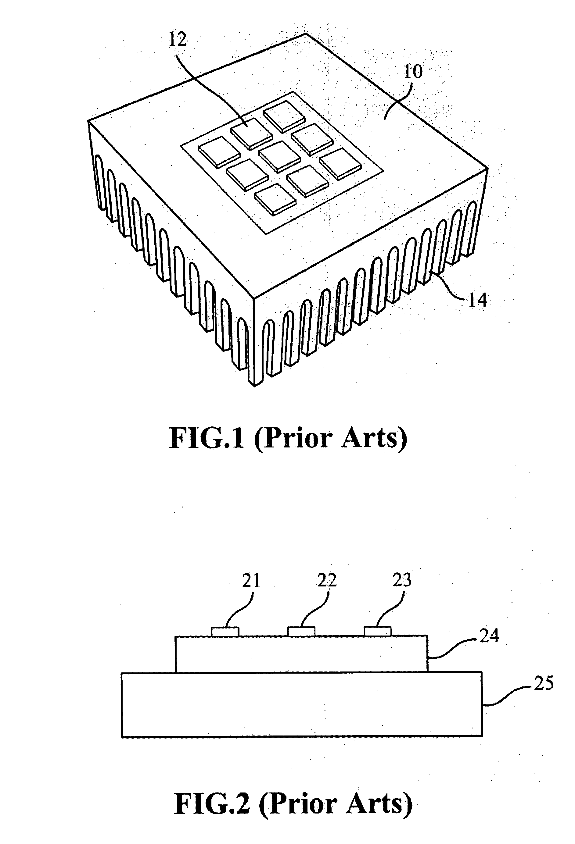
Because the distances between the LEDs 12 are too far, this lighting device cannot provide lighting effects similar to those of point light sources.
The disadvantage of the lighting device shown in FIG. 2 is that the control circuit 24 is too close to the LEDs.
When the LEDs generate heat, the operation of the control circuit 24 is easily affected and even damaged.

Method used


Image

  • System in Package High Power Highly Efficient Diode Lamp
  • System in Package High Power Highly Efficient Diode Lamp
  • System in Package High Power Highly Efficient Diode Lamp

Examples


Embodiment Construction

[0021]One main purpose of this invention is to provide a system-in-package, high power, and highly efficient diode lamp.

[0022]Please refer to FIG. 3(A) and FIG. 3(B), which respectively illustrate the lateral view and three-dimensional view of the diode lamp of one preferred embodiment according to this invention. The diode lamp 30, according to this invention, includes a heat-conducting / heat-dissipating module 31, an LED light module 32, a control circuit module 33, and an optical module 34. The heat-conducting / heat-dissipating module 31 includes a heat-conducting device 311 and at least one heat-dissipating fin 312. The LED light module 32 is mounted on a flat portion of the heat-conducting device 311. The optical module 34 is used for focusing light emitted by the LED light module 32. The control circuit module 33 is used for controlling the LED light module 32. When the diode lamp 30 is electrically connected to a power supply, the control circuit module 33 selectively controls ...


PUM


Abstract

A system in package, high power, and highly efficient diode lamp is provided. The diode lamp includes a heat-conducting / heat-dissipating module, a LED light module, an optical module, and a control circuit module. The heat-conducting / heat-dissipating module includes a heat-conducting device and at least one heat-dissipating fin. The LED light module is disposed on a flat portion of the heat-conducting device. The optical module focuses the light emitted by the LED light module. The control circuit module is used to control the LED light module. When the diode lamp is electrically connected to a power supply, the control circuit module selectively controls the LED light module to emit the light. The heat generated during the operation of the LED light module is conducted from the flat portion of the heat-conducting device to the at least one heat-dissipating fin, and then it is dissipated by the at least one heat-dissipating fin.

Description

BACKGROUND OF THE INVENTION[0001]1. Field of the Invention[0002]The present invention relates to diode lamps with high power and high efficiency. More specifically, the diode lamps in this invention are system-in-package lighting devices.[0003]2. Description of the Prior Art[0004]Because light-emitting diodes (LEDs) have many advantages, such as low power consumption, quick reaction, being shake-endurable, and being suited to mass production, lighting products that adopts LEDs as light sources are more and more popular. However, after being turned on for a while, the temperature of high power LEDs in prior arts will be too high. The lighting efficiency of LEDs is thus decreased, and their light intensity can not be further increased. Therefore, every product that adopts a high power and highly efficient LED needs good heat-dissipating mechanisms.[0005]Please refer to FIG. 1, which illustrates a lighting device integrated with a heat-dissipating device in prior arts. To increase the ...

Claims


Application Information

Patent Timeline
Patent Type & Authority Applications(United States)
IPC IPC(8): H01J61/52G02B27/20F21V9/00H01L33/50F21Y101/00H01L33/64
CPCF21K9/00F21V29/004F21Y2101/02H01L33/648F21V29/83F21V29/507F21V29/76F21V29/767F21V29/773F21V29/006F21V29/89F21Y2105/10F21Y2115/10F21V29/51F21Y2115/30
Inventor CHEN, JEN-SHYAN
Owner ENRAYTEK OPTOELECTRONICS
Learn More