Inductive devices and methods of making the same

a technology of inductive devices and circuits, applied in the field of electric devices, can solve the problems of increasing manufacturing costs, damage and failure of inductive devices or associated circuits, and achieving the effect of easy assembly

Inactive Publication Date: 2009-11-12
BUSWELL HARRIE R
View PDF19 Cites 20 Cited by
  • Summary
  • Abstract
  • Description
  • Claims
  • Application Information

AI Technical Summary

Benefits of technology

[0011]According to another aspect of the invention, the magnetic component(s) of an inductive device can be formed from a serpentine or other wire pattern wound onto a mandrel, and a toroidal electrical core may be wound on the same mandrel, thus enabling toroidal inductive devices to be easily assembled on a simple manufacturing apparatus.

Problems solved by technology

While improvements in the magnetic material used in inductive devices have been made, these improvements typically have been incremental.
Toroidal type transformers and inductors often have many desirable operational characteristics, but tend to be more costly to manufacture than the other two types mentioned above.
Also, the toroidal type devices have an inherent problem associated with heavy inrush currents, which can cause damage and failure to the inductive device or associated circuitry.
The inrush current problem is primarily due to a lack of magnetic gap control in conventional toroidal type devices.
Another common limitation relates to the use of geometries that perturb and distort magnetic fields present when the devices are in operation.
Laminate transformers and wound core transformers often require considerable handwork in manufacture.
Conventional toroidal type devices also involve manual construction operations that, even with the aid of complex machines, render them expensive to manufacture.
In some conventional devices, electrical windings are exposed to the environment, which can allow electromagnetic interference and flux losses from a conventional unit to the surrounding environment and can also subject the devices to external electromagnetic interference.
Further, conventional device designs may exhibit aberrations of the magnetic flux pattern as a result of electrical conductors having magnetic components disposed unevenly about them.
An uneven arrangement of magnetic material affects reluctance and perturbs flux pathways, thus also affecting the fundamental frequency and promoting undesirable harmonic activity.

Method used


Image

  • Inductive devices and methods of making the same
  • Inductive devices and methods of making the same
  • Inductive devices and methods of making the same

Examples


Embodiment Construction

[0058]The embodiments described below represent non-limiting examples of the present invention. In some instances, certain features are shown in exaggerated or enlarged form to facilitate a clearer understating of a particular embodiment.

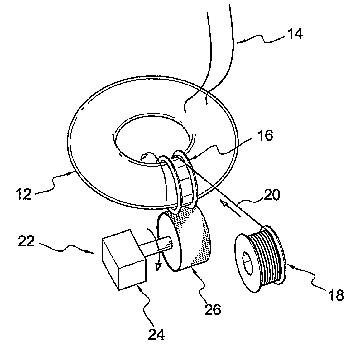
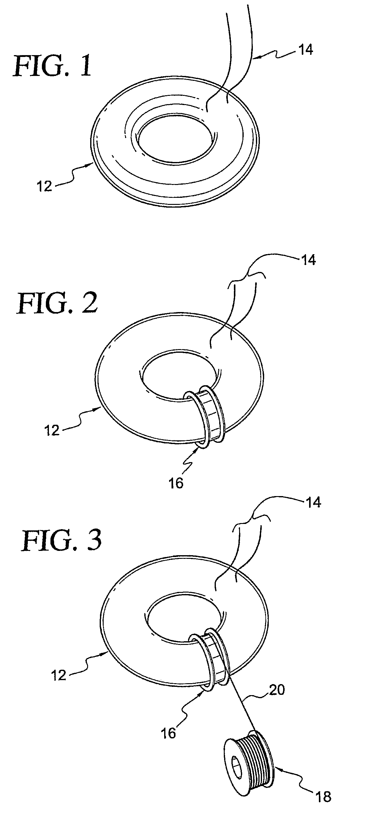
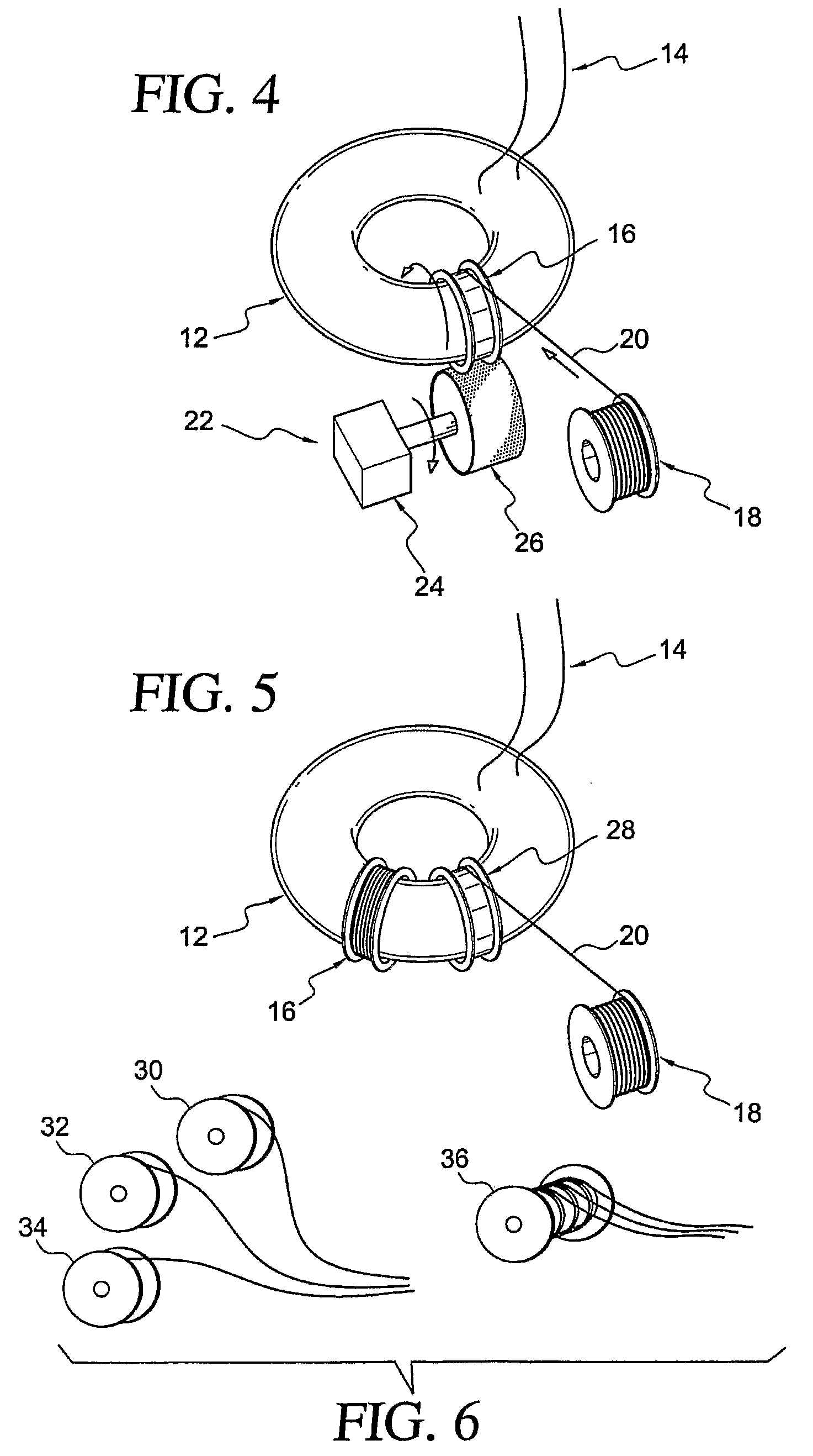
[0059]FIGS. 1-3 are diagrams for explaining a method of making a toroidal inductive device in accordance with the present invention. In particular, the method of making an inductive device can include providing a toroidal electrical core 12. The toroidal electrical core 12 can include electrical leads 14. The inductive device can be configured for use as an inductor, a choke, a transformer, or the like. The electrical core 12 can be formed of electrical wire or electrical strip, for example. The conductive material forming the electrical core 12 is preferably coated with an electrically insulating material. The toroidal shaped electrical core 12 provides a shape about which one or more magnetic components can be disposed so that the electrical core ...


PUM

PropertyMeasurementUnit
areaaaaaaaaaaa
magneticaaaaaaaaaa
cylindrical shapeaaaaaaaaaa

Abstract

Toroidal inductive devices are manufactured with high efficiency through the use of bobbin winding techniques or wound magnetic pattern members.

Description

CROSS-REFERENCE TO RELATED APPLICATIONS[0001]This application claims the benefit of U.S. Provisional Application No. 60 / 759,577, filed Jan. 18, 2006, entitled “Electrical Core Coils and Transformers and Processes For Making Same”; U.S. Provisional Application No. 60 / 759,567, filed Jan. 18, 2006, entitled “Inductive Devices and Process for Making Same”; and U.S. Provisional Application No. 60 / 759,566, filed Jan. 18, 2006, entitled “Inductive Devices and Process for Making Same,” each of which is incorporated herein by reference in its entirety.FIELD OF THE INVENTION[0002]This invention relates generally to the field of electrical devices and, more specifically, to inductive devices and methods for making the same.BACKGROUND OF THE INVENTION[0003]Conventional inductive devices, such as coils and transformers, have been used widely for over one hundred years. Inductive devices have applications in many areas of technology, including electric power distribution, motor and generators, po...

Claims


Application Information

Patent Timeline
Patent Type & Authority Applications(United States)
IPC IPC(8): H01F27/30H01F27/24H01F7/127
CPCH01F3/06H01F27/266H01F27/2828H01F27/30H01F30/06H01F41/0213Y10T29/49071H01F27/24
Inventor BUSWELL, HARRIE R.
Owner BUSWELL HARRIE R
Why Eureka
Try Eureka