GPS power savings using low power sensors

a low-power sensor and gps technology, applied in the field of electronic communication, can solve the problems of large positioning errors, large positioning errors, and large power consumption of position location functions

Active Publication Date: 2009-11-12
QUALCOMM INC
View PDF17 Cites 128 Cited by
  • Summary
  • Abstract
  • Description
  • Claims
  • Application Information

AI Technical Summary

Benefits of technology

[0013]In one embodiment, a computer-readable medium carrying one or more sequences; of one or more instructions for determining the position of a wireless device is disclosed. The one or more sequences of one or more instructions including instructions which, when executed by one or more processors, cause the one or more processors to perform steps of: detecting the availability of one or more positioning signals and determining a current position of the wireless device based upon the positioning signals. The instructions also cause the one or more processors to perform steps of determining the timing and duration of a power saving event, deactivating an SPS receiver, and suspending processing of the positioning signals in response to the power saving event if the positioning signals are detected as being available and the current position is obtained. The instructions also cause the one or more processors to perform steps of obtaining sensor data representative of a relative change in the position of the wireless device, updating the position of the wireless device from time to time based upon the sensor data during the power saving event, and activating the SPS receiver and resuming processing of the positioning signals after the power saving event.

Problems solved by technology

However, position location functions can consume substantial amounts of power and, in some cases, can significantly reduce the amount of time that a wireless device can be operated on battery power.
Infrequent updates may lead to large positioning errors.
This can be especially detrimental for navigation or for position location in the event of an emergency.

Method used


Image

  • GPS power savings using low power sensors
  • GPS power savings using low power sensors
  • GPS power savings using low power sensors

Examples


Embodiment Construction

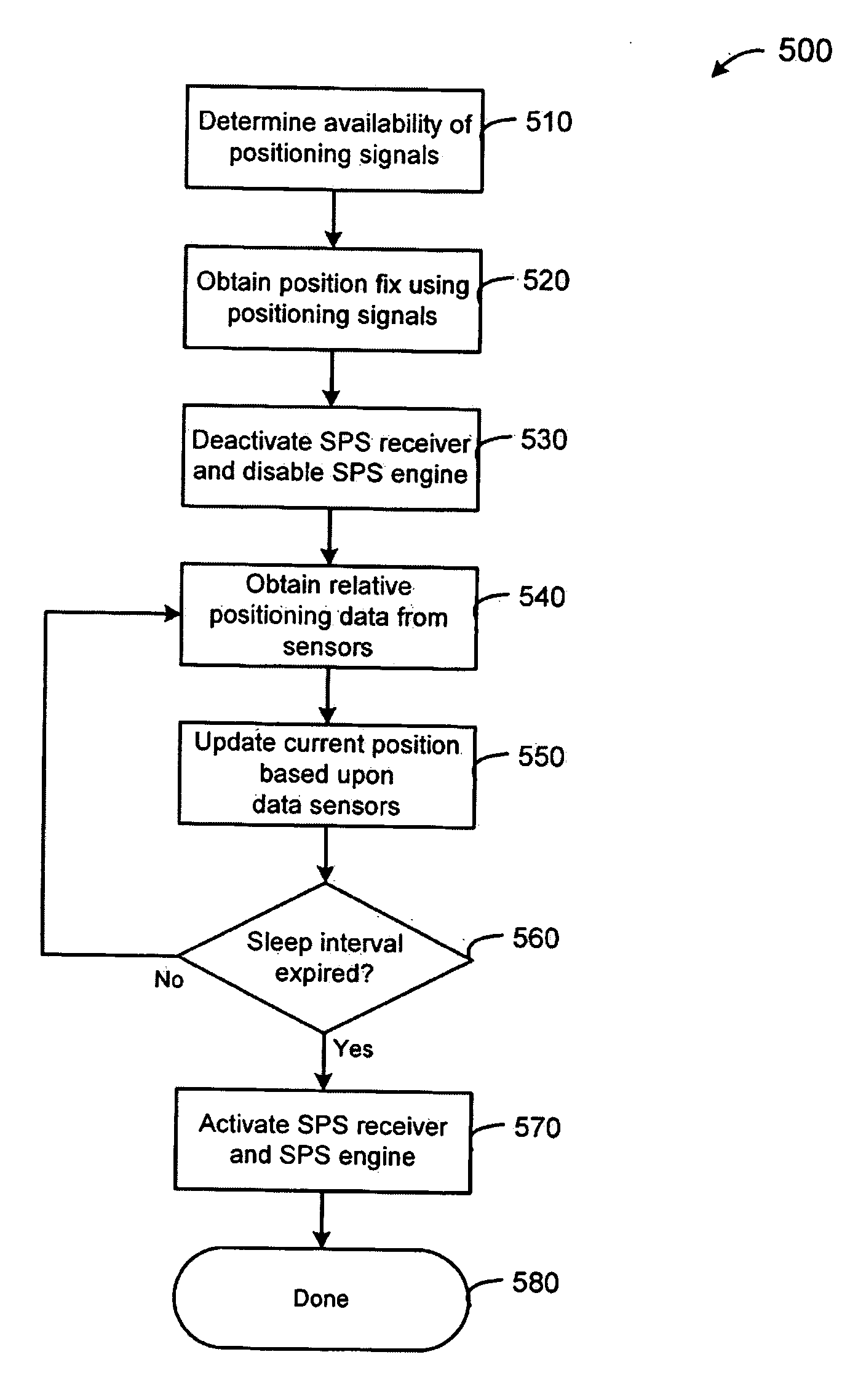
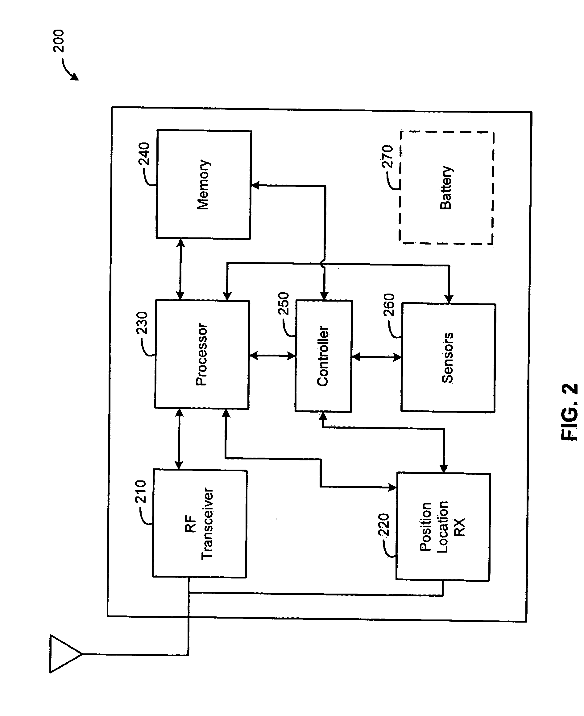
[0022]A position location system, apparatus, and method are disclosed. A wireless device includes a satellite positioning system (SPS) receiver and position location processor. The SPS receiver detects the availability of positioning signals and the position location processor determines an initial position of the wireless device based upon the positioning signals. A controller generates power saving events when the positioning signals are detected as being available. The controller determines the timing and duration of the power saving events. During a power saving event, the SPS receiver is deactivated and / or processing of the positioning signals is suspended to reduce power consumption of the wireless device. The initial position is updated based upon relative positioning information from one or more sensors during the power saving event. The controller activates the SPS receiver and resumes processing of the positioning signals following the power saving event.

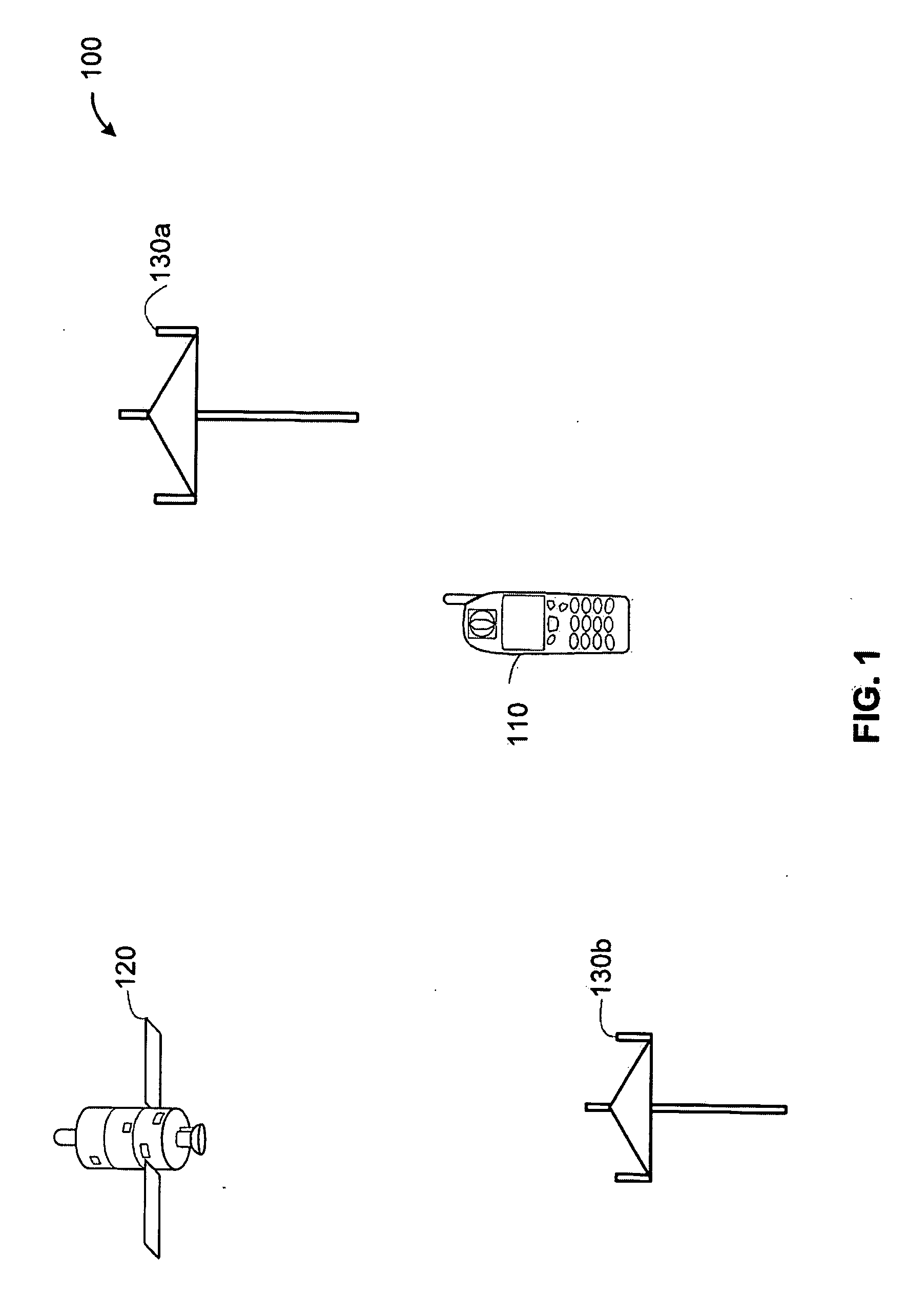
[0023]FIG. 1 is a ...


PUM


Abstract

A position location system, apparatus, and method are disclosed. A wireless device includes a satellite positioning system (SPS) receiver and position location processor. The SPS receiver detects the availability of positioning signals and the position location processor determines an initial position of the wireless device based upon the positioning signals. A controller generates power saving events when the positioning signals are detected as being available. The controller determines the timing and duration of the power saving events. During a power saving event, the SPS receiver is deactivated and/or processing of the positioning signals is suspended to reduce power consumption of the wireless device. The initial position is updated based upon relative positioning information from one or more sensors during the power saving event. The controller activates the SPS receiver and resumes processing of the positioning signals following the power saving event.

Description

FIELD OF THE DISCLOSURE[0001]This disclosure relates generally to electronic communications and, more particularly, to wireless position location systems.BACKGROUND OF THE DISCLOSURE[0002]In many applications it is advantageous to have the ability to determine a position of a wireless device. Position location capabilities may be helpful for navigation, tracking, or in the event of an emergency.[0003]Advances in the performance of portable electronics, particularly advances in the performance of processors, have added to the demand for using-position location with a variety of wireless devices.[0004]However, position location functions can consume substantial amounts of power and, in some cases, can significantly reduce the amount of time that a wireless device can be operated on battery power. This is because the same battery typically supplies-power for positioning functions as well as for other functions such as voice and data communications.[0005]Since the position of a wireless...

Claims


Application Information

Patent Timeline
Patent Type & Authority Applications(United States)
IPC IPC(8): G01S1/00H04B1/38
CPCG01S19/47G01S19/34G01C21/12
Inventor GOPINATH, SUNIL
Owner QUALCOMM INC
Why Eureka
Try Eureka