Color image display device and color conversion device

a color conversion device and display device technology, applied in the direction of television systems, instruments, color signal processing circuits, etc., can solve problems such as unnatural reproduction, and achieve the effect of extending the color reproduction range and enhancing saturation

Active Publication Date: 2009-11-12
SHARP KK
View PDF14 Cites 40 Cited by
  • Summary
  • Abstract
  • Description
  • Claims
  • Application Information

AI Technical Summary

Benefits of technology

[0023]According to the present invention, since a color is reproduced with an original hue of an input video signal in the first color range and a color is reproduced with enhanced saturation while changing a hue gradually to extend a color reproduction range, a vivid video can be reproduced without giving uncomfortable feeling by making good use of a wide color reproduction range of a display device.

Problems solved by technology

However, since saturation is increased in overall display due to the wider color reproduction ranges, colors are unnaturally reproduced such as a light blue sky is turned to be a deep blue sky or human skin to be yellow.

Method used


Image

  • Color image display device and color conversion device
  • Color image display device and color conversion device
  • Color image display device and color conversion device

Examples


first embodiment

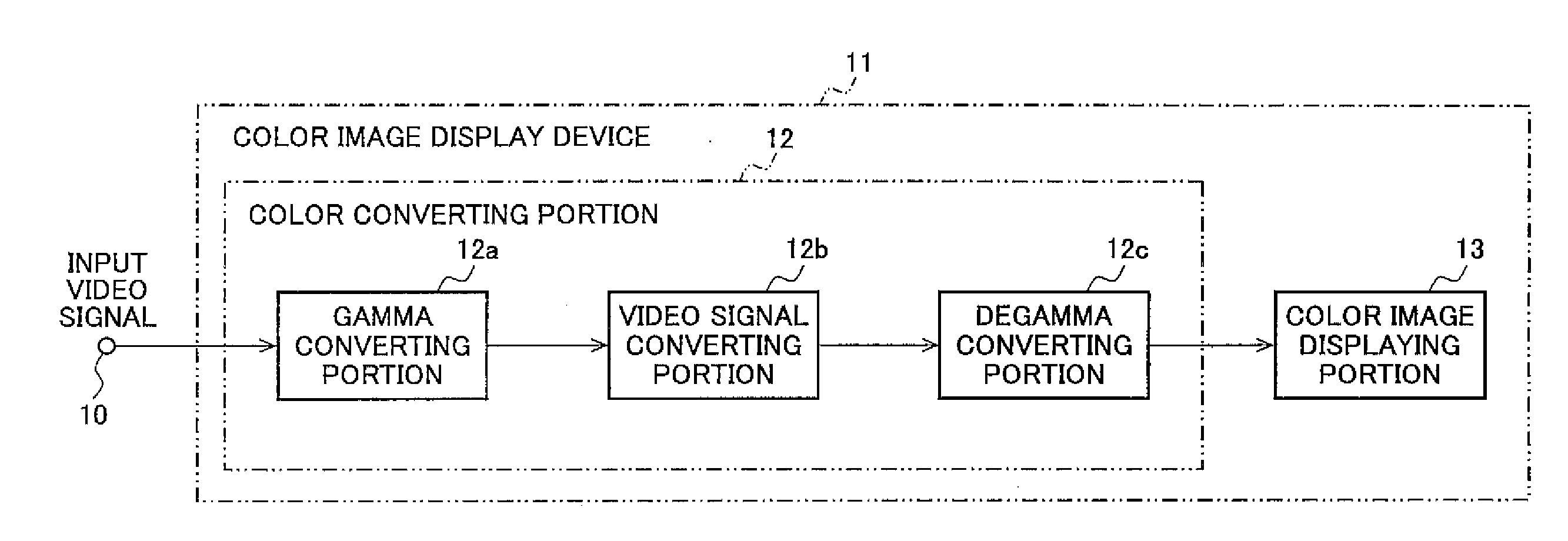
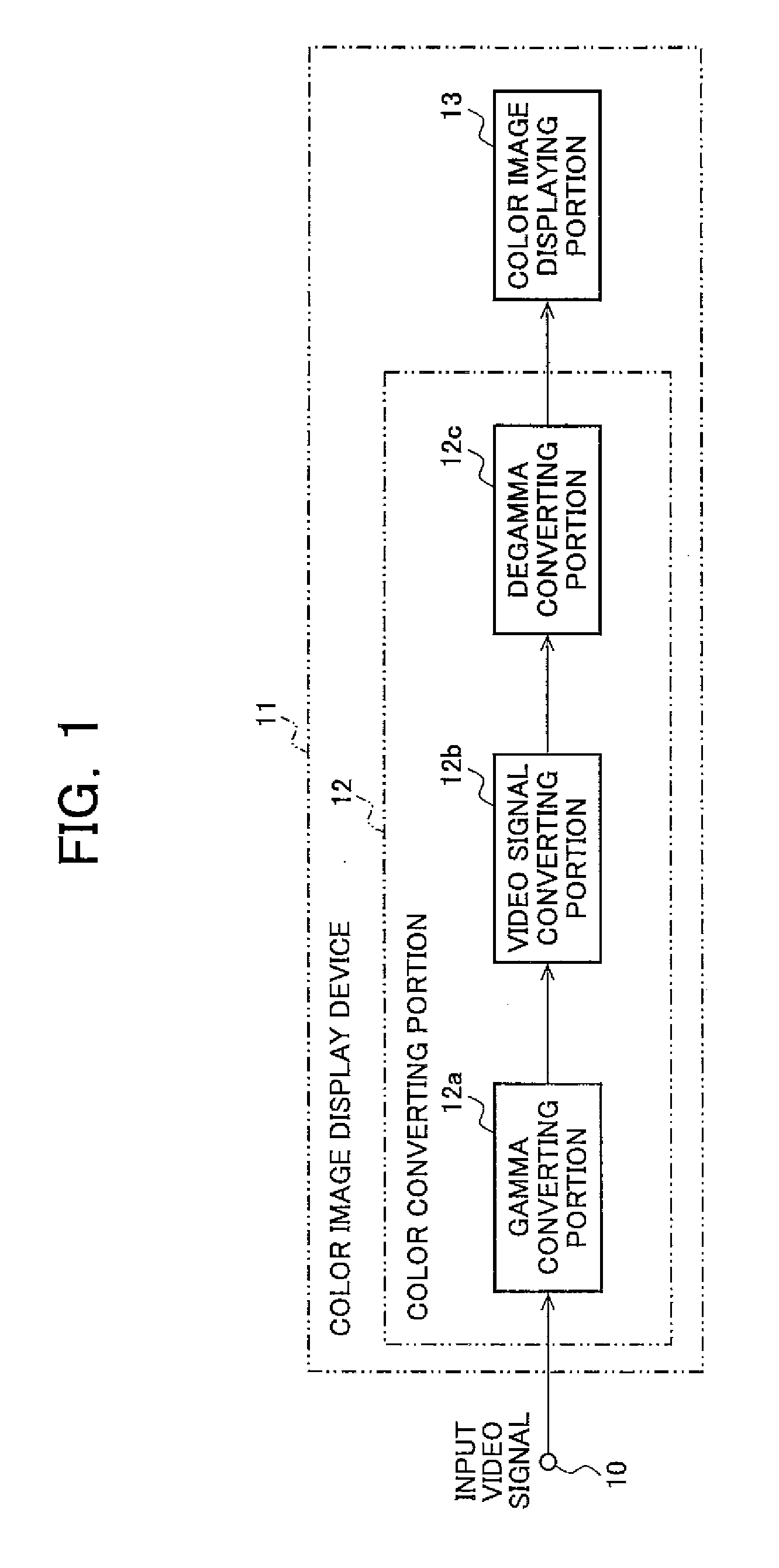
[0040]FIG. 1 is a block diagram of an exemplary configuration of a display device according to a first embodiment of the present invention; in FIG. 1, a reference numeral 10 denotes an input video signal; 11 denotes a color image display device; 12 denotes a color converting portion; and 13 denotes a color image displaying portion. The input video signal 10 is color-converted by the color converting portion 12 and displayed by the color image displaying portion 13.

[0041]The color converting portion 12 corresponds to a color conversion device of the present invention, and includes a gamma converting portion 12a that performs gamma conversion for the input video signal10, a video signal converting portion 12b that performs a converting processing of a gamma-converted RGB signal, and a degamma conversion portion 12c that performs degamma conversion using the inverse function of gamma characteristics of the color image displaying portion 13. These portions will be described in detail la...

second embodiment

[0103]A second embodiment of the present invention will then be described.

[0104]This embodiment is an example of a method for defining the third color space without LUT or weighting correction mentioned in the first embodiment in such a case that the color reproduction range of the display device is not so much larger than that in the first color space and the transfer function of the display device can be represented by a matrix.

[0105]Although the first color space is divided into a plurality of color ranges and each color range is converted to the third color space in the first embodiment, the entire first color space is once converted to a virtual color space (hereinafter, fourth color space) larger than the second color space of the display device and the third color space is defined as a color space converted from the fourth color space so as to fall within the second color space in this embodiment.

[0106]A specific method of defining the third color space will be described belo...

third embodiment

[0128]A third embodiment of the present invention will then be described.

[0129]In the second embodiment, the sums of positive elements of the lines of Eq. 26 indicate how many times of the emission before the conversion corresponds to the maximum emission of red / blue / green LEDs after the conversion. Therefore, it is desirable that each of the sums is one for every LED. Since the sum of the first line corresponding to red is 0.828 in Eq. 26, a value greater than 0.828×255 does not appear after the conversion in red and green for any input video signal in this example, and the dynamic range of the color image displaying portion 13 is narrowed. The sum of positive elements of each line may be approximated to one to expand the dynamic range by individually changing the maximum emission amounts of the LEDs.

[0130]If the LED drive current is increased to increase an emission amount, a signal value of color corresponding to the LED may be reduced when a certain color is displayed. Therefore...


PUM


Abstract

A color image display device is provided to reproduce colors determined by an input video signal in a color space of the display device while keeping a wide color reproducing region of the display device with natural hues. On the assumption that a color space is hypothetically considered so that an input signal is originally in hue in a first color range while an increasing saturation is reproduced with hues changed gradually to a widening direction of color reproduction in a second color range or more, the color converting portion 12 converts a video signal, so that an input video signal 10 is reproduced on a color image displaying portion 13 with a tristimulus value represented in this hypothetical color space, and the color image displaying portion 13 displays, and reproduces, a vivid video image without a feeling of wrongness by making use of a wide color reproduction range of the color image display device.

Description

TECHNICAL FIELD[0001]The present invention relates to a color image display device and a color conversion device, and, more particularly, to a color image display device and a color conversion device performing color conversion of video signals.BACKGROUND OF THE INVENTION[0002]Recently, from a viewpoint of environment issues such as mercury-less, and for realizing a long-lived device, semiconductor light sources such as LED (light emitting diode) and laser are actively used as light sources for color image display devices. Major advantages of using semiconductor light sources include that displays with wide color reproduction ranges may be realized. This is because semiconductor light sources have sharp spectrums, and color image display devices using semiconductor light sources for three primary colors of red, green, and blue may have wider color reproduction ranges as compared to conventional color image display devices such as CRT (cathode ray tube) displays and liquid crystal di...

Claims


Application Information

Patent Timeline
Patent Type & Authority Applications(United States)
IPC IPC(8): H04N11/20
CPCG09G5/02G09G2340/06H04N9/67H04N9/3111H04N1/6058
Inventor IMAI, TAKUMIIWAUCHI, KENICHI
Owner SHARP KK
Why Eureka
Try Eureka