Liquid crystal cell and a display

a liquid crystal cell and display technology, applied in the field of liquid crystal cells, can solve the problems of not being able to easily switch off to allow viewing, never achieving privacy in a plane parallel to the microlouvre groove, and adding bulk to the display, so as to prevent, reduce, and improve the effect of privacy

Active Publication Date: 2009-11-12
SHARP KK
View PDF28 Cites 7 Cited by
  • Summary
  • Abstract
  • Description
  • Claims
  • Application Information

AI Technical Summary

Benefits of technology

[0039]It has been found that a particularly good private viewing mode may be obtained when circularly polarised light, or elliptically polarised light with a non-zero ellipticity, passes through the liquid crystal layer, as compared to when linearly polarised light passes through the liquid crystal layer.
[0040]In the liquid crystal cell of the first aspect, the retarder is provided to prevent, or reduce, colouring effects when the liquid crystal material is switched to give a wide display mode. In principle, the retarder may be omitted, for example if the liquid crystal cell is for use in an application in which colouring effects can be tolerated or if a retarder is placed elsewhere in the optical path.

Problems solved by technology

However, the film is not switchable so must it be physically positioned / removed to change between one viewing mode and another.
Another drawback of the 3M microlouvre is that the there is never any privacy achieved in a plane parallel to the microlouvre grooves.
However none of them can easily be switched off to allow viewing from a wide range of angles.
This method has the disadvantages that it contains moving parts which may fail or be damaged and which add bulk to the display.
They share the disadvantage that the light control film always absorbs a significant fraction of the light incident upon it, whether the display is in public or private mode.
The display is therefore inefficient in its use of light.
A first disadvantage of this method is difficulty and expense of manufacturing liquid crystal cells with an appropriate shape.
A second disadvantage is that in the private mode, a ray of light may enter at an angle such that it passes first through the transparent material and then through part of a liquid crystal cell.
Such a ray will not be completely absorbed by the liquid crystal cell and this may reduce the privacy of the device.
Although such an arrangement may be used to provide a privacy mode, it is not switchable.
In particular, the relatively narrow range of viewing angles throughout which the non-fixed image can be seen cannot be changed if non-private operation is desired.

Method used


Image

  • Liquid crystal cell and a display
  • Liquid crystal cell and a display
  • Liquid crystal cell and a display

Examples


Embodiment Construction

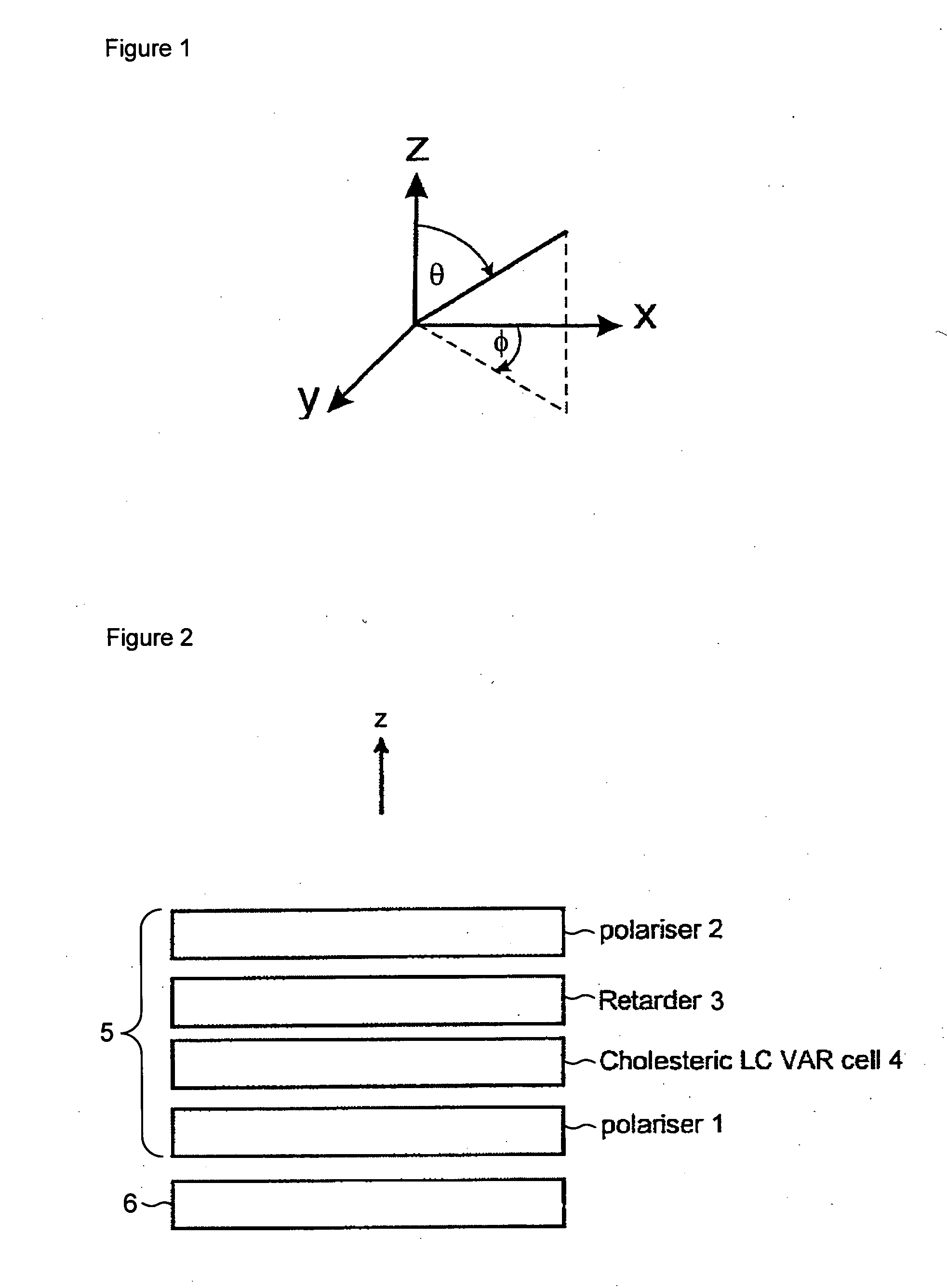
[0067]FIG. 1 illustrates the co-ordinate system used in this application. It is assumed that a display face is parallel to the x-y plane, and that light propagates generally along the z-direction. The out-of-plane angle, or polar angle, represents the angle between a direction and the z-axis, and is denoted by q. The in-plane angle, or azimuth angle, represents the angle between the x-axis and a projection of a direction on the x-y plane, and is denoted by f.

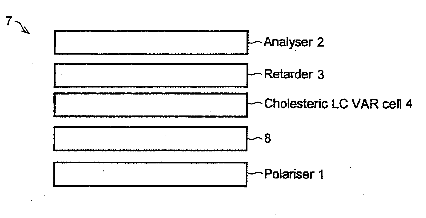
[0068]FIG. 2 is a schematic sectional view of a liquid crystal cell 5 of the present invention. The liquid crystal cell 5 comprises a cholesteric liquid crystal cell 4 and a retarder 3 and disposed in an optical path through the cholesteric liquid crystal cell 4. The cholesteric liquid crystal cell 4 contains a layer of cholesteric material disposed between upper and lower transparent substrates (not shown). Other components of the cholesteric liquid crystal cell 4 such as, for example, electrodes to allow the layer of cholester...


PUM

PropertyMeasurementUnit
twist angleaaaaaaaaaa
viewing angleaaaaaaaaaa
refractive indexaaaaaaaaaa

Abstract

A liquid crystal cell (5) comprises a layer (4) of cholesteric liquid crystal material; and a retarder (3) disposed in an optical path through the layer (4) of cholesteric liquid crystal material. The cholesteric liquid crystal material is switchable between a first state in which it cooperates with the retarder (3) to provide a first viewing angle range and a second state in which it cooperates with the retarder (3) to provide a second viewing angle range which is smaller than the first viewing angle range. The pitch of the cholesteric liquid crystal material is greater than an intended wavelength of operation of the liquid crystal cell divided by the average refractive index of the liquid crystal material. The liquid crystal cell may be used as a Viewing Angle Restriction (VAR) element, to enable another component, such as a display panel (6), to be operated in either a wide viewing mode or a narrow viewing mode.

Description

TECHNICAL FIELD[0001]The present invention relates to a liquid crystal cell that may be controlled to provide either a first viewing angle range or a second viewing angle range which is smaller than the first viewing angle. Such a liquid crystal cell may be placed, for example, in front of a display to enable the viewing angle range of the display to be controlled. The present invention also relates to a display, the viewing angle range of which may be controlled.BACKGROUND ART[0002]Electronic display devices, such as monitors used with computers and screens built in to telephones and portable information devices, are usually designed to have a viewing angle as wide as possible so that they can be read from any viewing position. However, there are some situations where a display which is visible from only a narrow range of angles is useful. For example, one might wish to read a private document using a portable computer while on a crowded train.[0003]A number of devices are known wh...

Claims


Application Information

Patent Timeline
Patent Type & Authority Applications(United States)
IPC IPC(8): G02F1/13363G02F1/1335
CPCG02F1/1323G02F1/133634G02F2413/11G02F2413/01G02F1/13718G02F1/1335G02F1/1347
Inventor SMITH, NATHAN J.GASS, PAUL A.BALL, JAMES M.TILLIN, MARTIN D.SAGARDOYBURU, MICHEL
Owner SHARP KK
Why Eureka
Try Eureka