Apparatus for measuring pressure in a vessel using magnetostrictive acoustic transducer
a technology of magnetostrictive acoustic transducer and pressure measurement apparatus, which is applied in the direction of fluid pressure measurement, fluid pressure measurement using inductance variation, instruments, etc., can solve the problems limitation of capacitance diaphragm gauge, and inside of the vessel must be vacuum sealed, so as to increase the ultrasonic transmitting efficiency and minimize leakage. the effect o
- Summary
- Abstract
- Description
- Claims
- Application Information
AI Technical Summary
Benefits of technology
Problems solved by technology
Method used
Image

Examples
first embodiment
Method of First Embodiment
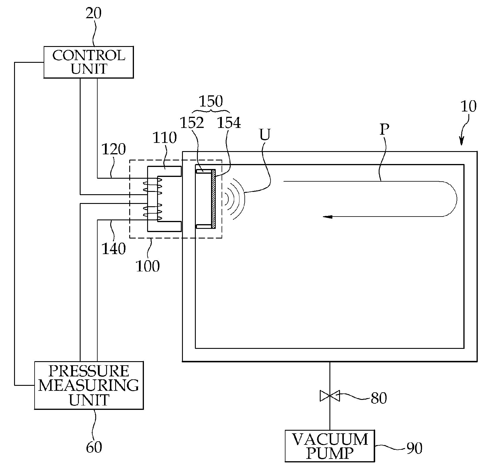
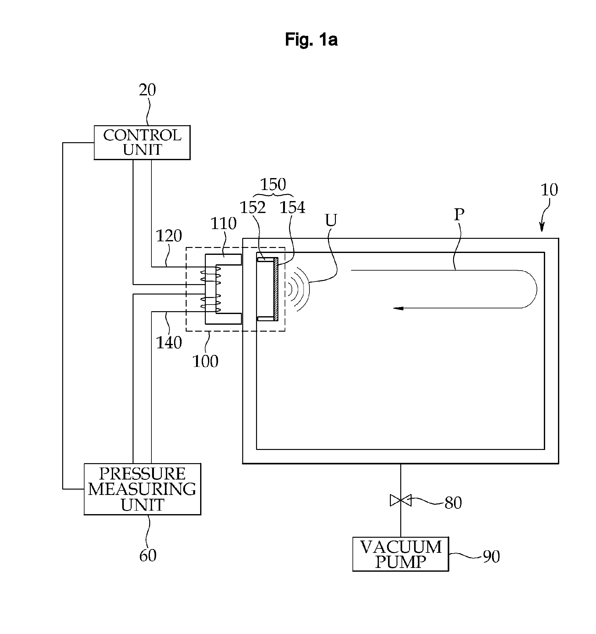
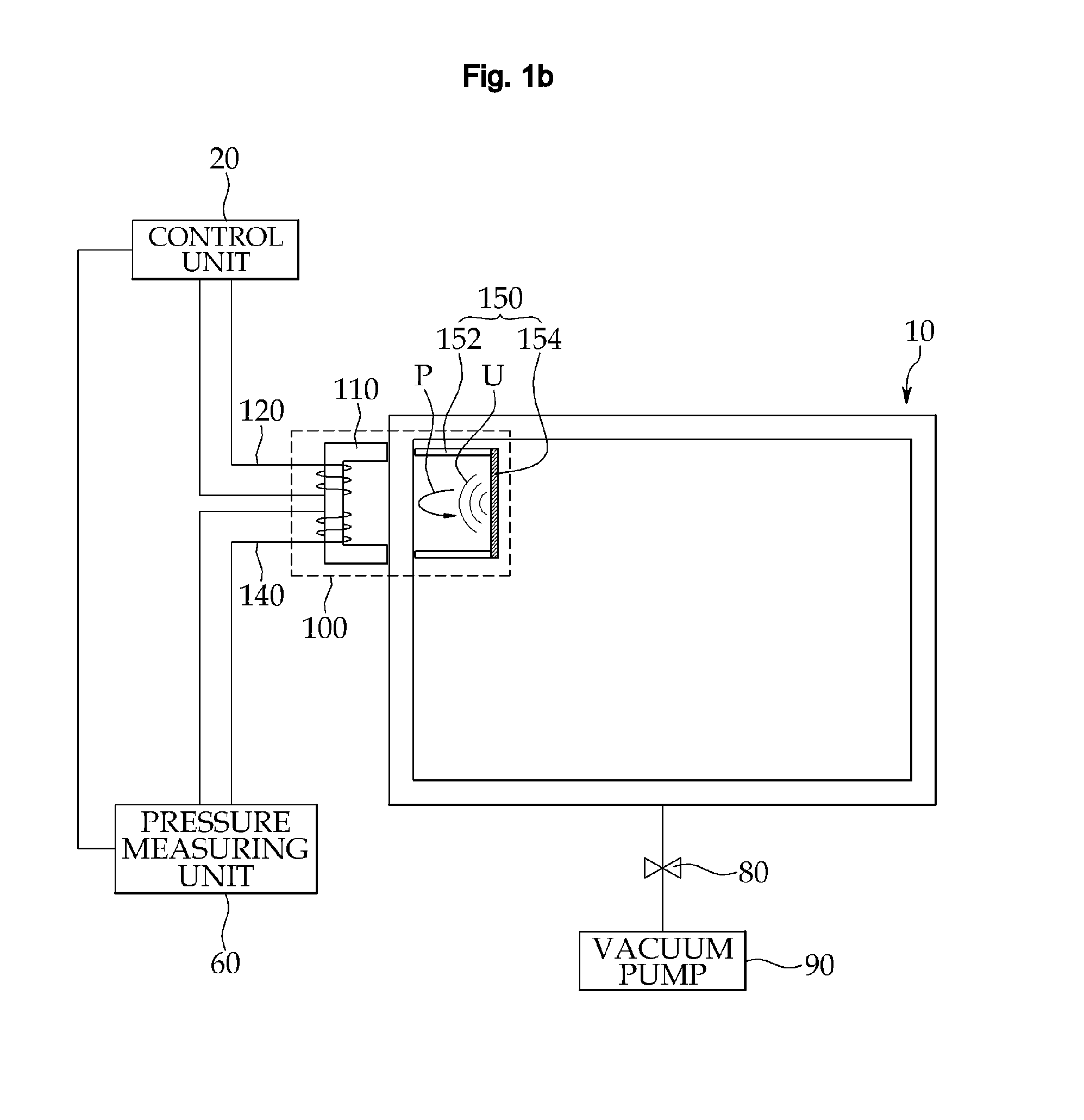
[0065]A method of measuring an internal pressure of the vessel 10 using the magnetostrictive exciting / receiving transducer 100 according to a first embodiment of the present invention is as follows. First, the pressure measuring apparatus is constructed (S10).
[0066]The excitation current signal of a predetermined value is supplied to the exciting coil unit 120 under current control of the control unit 20. When the current flows through the exciting coil unit 120, a magnetic field is induced to the first magnetization yoke 110 having the exciting coil unit 120 wound thereon. The induced magnetic field enables the magnetostrictive vibrating membrane 154 of the vibration unit 150, disposed inside the vessel 10, to vibrate, which generates ultrasonic waves (S20).
[0067]The generated ultrasonic waves travel inside the vessel 10. The traveling ultrasonic waves are reflected from the inner face of the vessel wall 10 and then returns back to the magnetostrictive exc...
second embodiment
Method of Second Embodiment
[0073]A method of measuring pressure inside the vessel using the magnetostrictive exciting / receiving transducer 100 according to a second embodiment of the present invention is almost the same as that of the first embodiment. The method of the second embodiment differs from the method of the first embodiment in that the travel path P of ultrasonic waves traveling inside the vessel 10 becomes short since the reflection plate 190 is further included as shown in FIG. 2. Since the travel path P of the ultrasonic waves becomes short, the sensitivity of the pressure measuring unit is increased. Accordingly, accuracy in measuring an internal pressure of the vessel 10 can be improved.
[0074]The control unit 20 can control the excitation current signal, which is supplied to the exciting coil unit 120, such that a resonance of ultrasonic waves is induced between the vibration unit 150 and the reflection plate 190. This is also for the purpose of increasing the sensit...
third embodiment
Method of Third Embodiment
[0075]In a method of measuring pressure inside the vessel using the pressure measuring apparatus employing the magnetostrictive acoustic transducer according to a third embodiment of the present invention, the pressure measuring apparatus is constructed almost identically to the method of the first embodiment. The method of the third embodiment differs from the method of the first embodiment in that the vibration unit 150, comprising the magnetostrictive vibrating element 156 and the acoustic impedance matching layer 158, is disposed inside the vessel 10 as shown in FIG. 3.
[0076]What a magnetic field is induced from the magnetostrictive exciting transducer 200 in response to the excitation current signal of the control unit 20 is identical to the method of the first embodiment. The magnetostrictive vibrating element 156 generates ultrasonic waves under the influence of the magnetic field induced by the exciting coil unit 120. The transmitting efficiency of ...
PUM
 Abstract
Description
Claims
Application Information
 - R&D
- Intellectual Property
- Life Sciences
- Materials
- Tech Scout
- Unparalleled Data Quality
- Higher Quality Content
- 60% Fewer Hallucinations
Browse by: Latest US Patents, China's latest patents, Technical Efficacy Thesaurus, Application Domain, Technology Topic, Popular Technical Reports.
© 2025 PatSnap. All rights reserved.Legal|Privacy policy|Modern Slavery Act Transparency Statement|Sitemap|About US| Contact US: help@patsnap.com