

Brain function analysis apparatus
a brain function and apparatus technology, applied in the field of brain function analysis methods and brain function analysis programs, can solve problems such as strong doubts about their effectiveness
- Summary
- Abstract
- Description
- Claims
- Application Information
AI Technical Summary
Benefits of technology
Problems solved by technology
Method used
Image

Examples
first embodiment
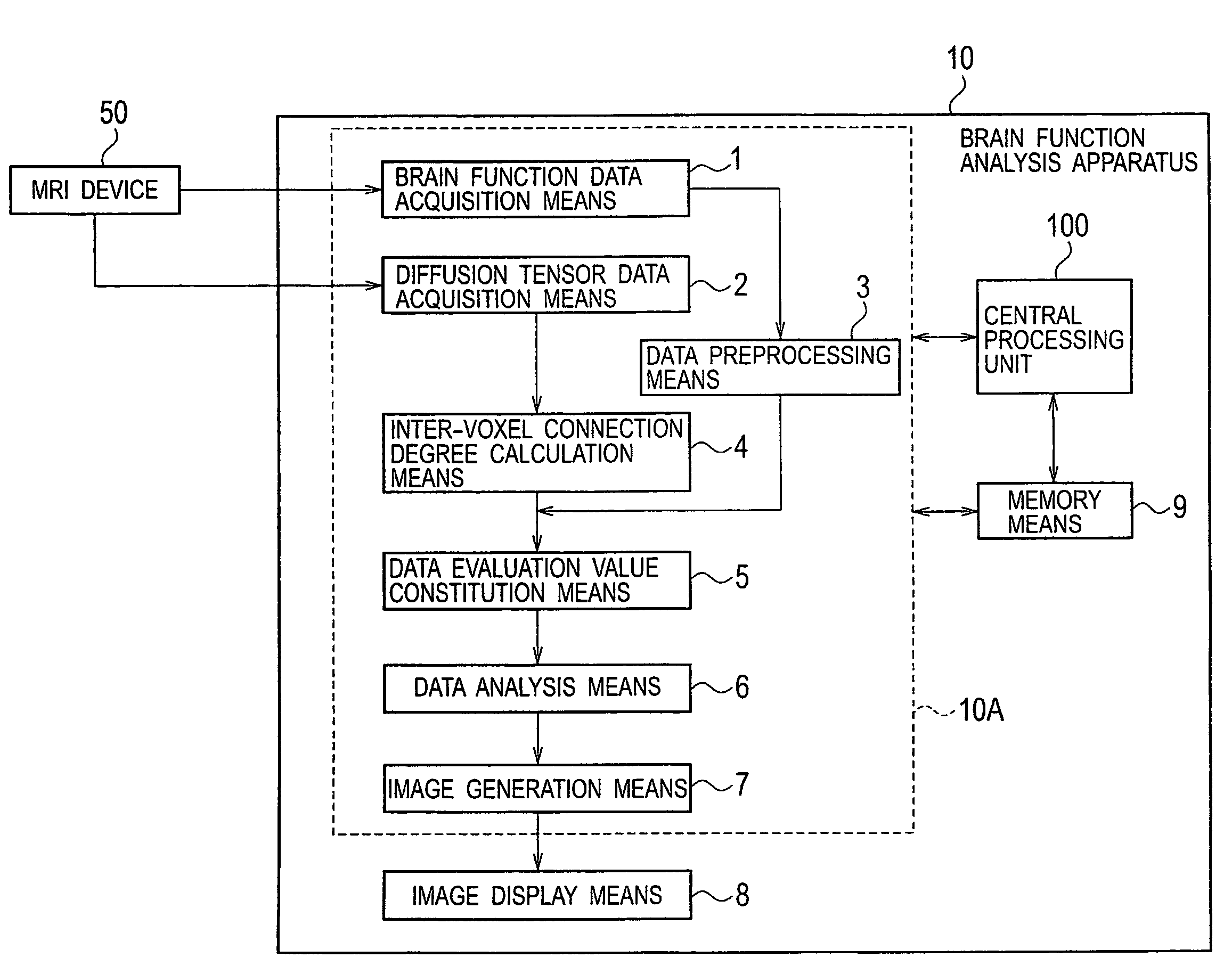
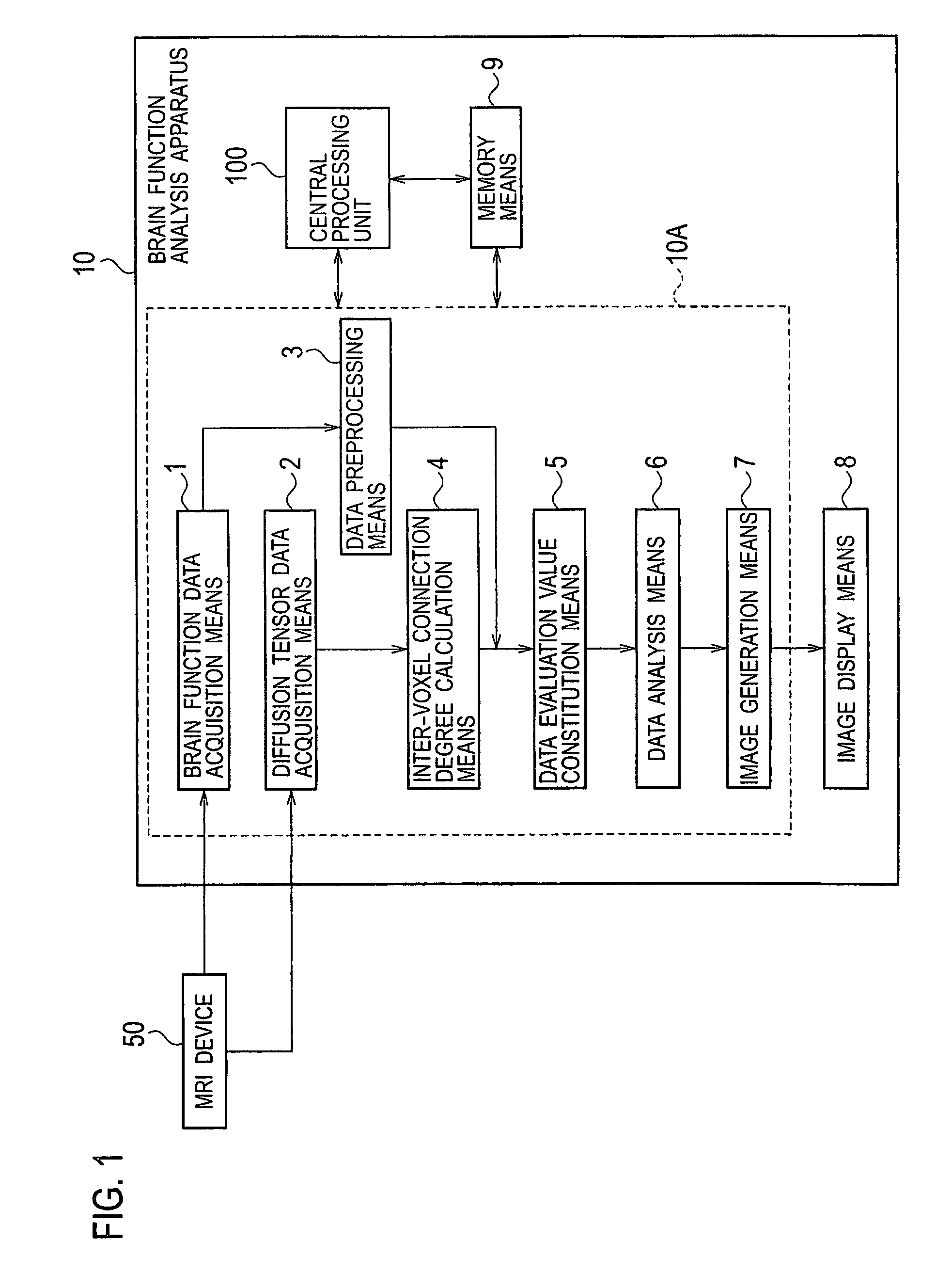
[0045]FIG. 1 is a block diagram showing a schematic configuration of a brain function analysis apparatus in accordance with a first embodiment of the present invention. A brain function analysis apparatus 10 of the first embodiment is provided with brain function data acquisition means 1 for acquiring original time series data ρ′(l, m, k, i) (for example, Equation (3)) of brain function information which is measured by an MRI device 50; diffusion tensor data acquisition means 2 for acquiring diffusion tensor data D(l, m, k) (for example, Equation (2)) which is measured also by the MRI device 50; data preprocessing means 3 for pre-processing the original time series data ρ′(l, m, k, i) of the brain function information which is acquired by the brain function data acquisition means 1; inter-voxel connection degree calculation means 4 for calculating a connection degree vector {right arrow over (C)}(l,m,k) representing a connection degree between voxels adjacent to each other from the ...
modified example 1 of first embodiment
[0120]In the first embodiment, the data analysis means 6 performs the nonparametric regression analysis by using the linear regression equation of Equation (19) at Step S50, but more strictly, it is also considered that the regression expression is performed with general n-dimensional functions, such as a quadratic function, a cubic function, or the like. Upon performing such a nonlinear regression analysis, Neural Network models can be used. As a typical Neural Network model, there is a hierarchical type Neural Network model composed of an input layer, a middle layer, and an output layer.
[0121]In the present modified embodiment, at Step S40 the data evaluation value constitution means 5 constitutes an evaluation value, in which an evaluation value for evaluating the continuity between adjacent voxels based on the connection degree vector {right arrow over (C)}(l,m,k) calculated by the inter-voxel connection degree calculation means 4 is added to a term of a square error which is an...
modified example 2 of first embodiment
[0124]The data evaluation value constitution means 5 constitutes at Step S40 the evaluation value Q of Equation (23) using the time series data ρ(l, m, k, i) of the brain function as the explaining variable, and φ(i) as the explained variable in the first embodiment, whereas, in the present modified embodiment, an evaluation value Q′″, for example,
Q′′′=1I∑i=1I{ρ(l,m,k,i)-ρ^(l,m,k,i)}2+κI∑i=1I[Cl(l,m,k){ρ^(l+1,m,k,i)-ρ^(l,m,k,i)}2+Cm(l,m,k){ρ^(l,m+1,k,i)-ρ^(l,m,k,i)}2+Ck(l,m,k){ρ^(l,m,k+1,i)-ρ^(l,m,k,i)}2](29)
is constituted for every voxel (l, m, k) by using the reverse relationship, namely, using φ(i) as the explaining variable, and ρ(l, m, k, i) as the explained variable. Here the following constraint condition:
ρ^(l,m,k,i)=∑l=1L∑m=1M∑k=1Ka^(l,m,k)φ(i)+b(30)
is given.
[0125]Subsequently, at Step S50 the data analysis means 6 determines an optimal κ using the Cross Validation method in order to determine the minimum value of the evaluation value Q′″ constituted as described above, and ...
PUM
 Abstract
Description
Claims
Application Information