

Combine harvester
- Summary
- Abstract
- Description
- Claims
- Application Information
AI Technical Summary
Benefits of technology
Problems solved by technology
Method used
Image

Examples
Embodiment Construction
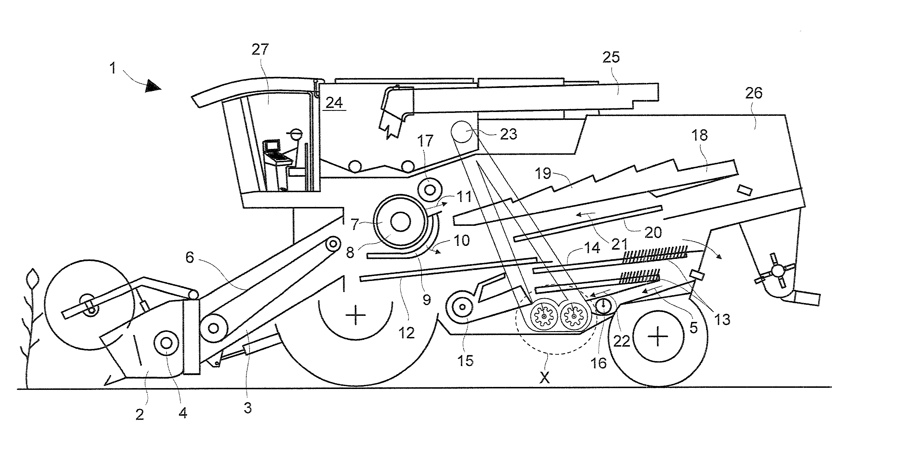
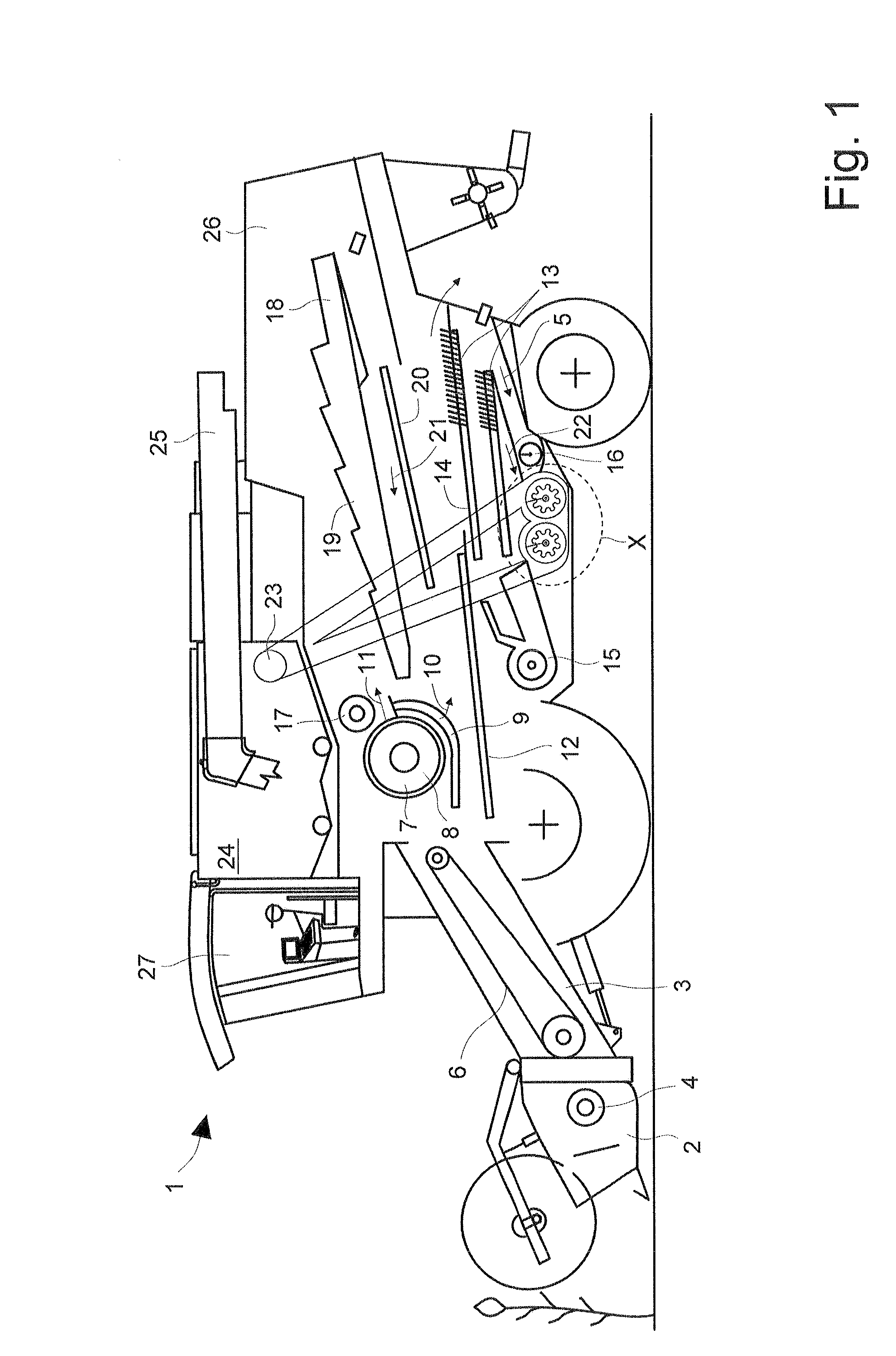
[0029]Combine harvester 1 shown schematically in FIG. 1 is composed of a support frame which is connected to the ground drive, and on which a multiple-component machine housing 26 is mounted. To protect the driver of combine harvester 1 from disturbing environmental influences, a closed driver's cab 27 is located in the front region. Combine harvester 1 includes a grain-cutting device 2 which is connected in a manner known per se to feed rake 3 of combine harvester 1. Cross auger component 4 of header 2 transfers the crop material to feed rake 3 which transfers the crop material via circulating conveyor 6 in its upper, rear region to threshing mechanism 7 of combine harvester 1. In threshing mechanism 7, which may be designed to include one cylinder or several cylinders, the crop material is conveyed between cylinders 8 and a concave 9 which at least partially encloses cylinders 8, thereby separating it into at least two sub-streams 10, 11. First sub-stream 10 is composed essentiall...
PUM
 Abstract
Description
Claims
Application Information