
Drive device for at least one machine auxiliary unit

a technology of auxiliary units and drive devices, which is applied in the direction of gearing, gearing elements, hoisting equipments, etc., can solve problems such as rotary vibrations

Inactive Publication Date: 2009-11-12
DR ING H C F PORSCHE AG
View PDF7 Cites 1 Cited by
  • Summary
  • Abstract
  • Description
  • Claims
  • Application Information

AI Technical Summary

Benefits of technology

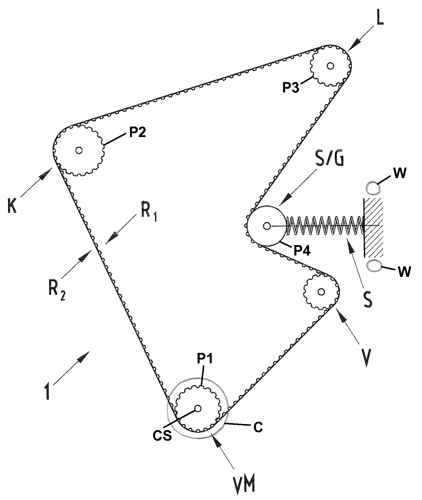
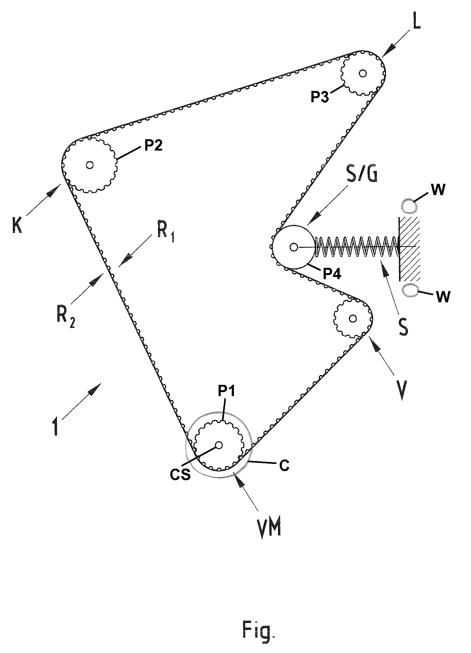
[0010]The invention uses a belt to correct the mechanical coupling between an internal combustion engine and an electrical machine. More particularly, the belt has a special configuration for introducing the force into the belt separately from the transmission of the force to the electrical machine. The preferred belt has a tooth system on one side and a poly-V on the opposite side. The electrical machine may have a poly-V-belt pulley and the internal combustion engine may have a toothed crankshaft belt pulley to drive the toothed side of the belt for transmitting the drive force of the internal combustion engine. Alternatively, the electrical machine may have a toothed belt pulley and the internal combustion engine may have a poly-V-belt pulley to drive the poly-V side of the belt for transmitting the drive force of the internal combustion engine. The interlocking connection between the toothed side of the belt and the toothed belt pulley provides reliable transmission of a strong torque between the internal combustion engine or machine and the electrical machine. The use of the poly-V-side of the belt for transmitting the torque between the belt and the poly-V-belt pulley provides a high level of damping of possible rotary vibrations due to slipping. The belt can transmit a torque from the internal combustion engine or machine to the electrical machine (generator operation of the electrical machine) and also can transmit a torque from the electrical machine to the internal combustion engine or machine (motor operation of the electrical machine). This novel use of a combined V- and toothed belt enables a reliable transmission of a high torque between the crankshaft and the electrical machine without a high level of vibrational loading that would lead to a weakening of the belt or to the production of noise by the belt. As an alternative, the belt side of the belt opposite the toothed side can have a configuration other than the poly-V.
[0014]A clutch, such as a magnetic clutch, preferably is provided for decoupling the belt or the belt pulley from the crankshaft. The clutch enables air-conditioning when the motor vehicle is stationary and when the internal combustion engine is turned off. To this end, the starter / generator is operated as a motor that uses the belt to drive the air-conditioning compressor. Therefore, the internal combustion engine need not rotate together with the starter / generator because the crankshaft has been decoupled. A further advantage is the option of decoupling the starter / generator when the battery is fully charged. Therefore, the belt drive could be decoupled from the internal combustion engine, for example, when an electrical air-conditioning arrangement is present and the air-conditioning system is switched off. Thus, no additional torque would be required for driving the starter / generator.

Problems solved by technology

The problem of rotary vibrations occurs primarily when coupling an electrical machine or a generator due to its high moment of inertia.

Method used


Image

  • Drive device for at least one machine auxiliary unit
  • Drive device for at least one machine auxiliary unit

Examples


Embodiment Construction

[0016]A drive device in accordance with the invention is identified by the numeral 1 in the FIGURE and is associated with machine auxiliary units K, L, S / G, which in this case are an air-conditioning compressor K, a power steering pump L and a starter / generator S / G. The drive device 1 is driven by a machine VM, in this case an internal combustion engine. The internal combustion engine VM has a crankshaft CS and a corresponding belt pulley P1 for driving the drive device 1. A belt B is mounted to the internal combustion engine belt pulley P1 to drive the belt pulleys P2, P3, P4 of the respective machine auxiliary units K, L, S / G. A deflection roller V also is provided. The belt B is a combined toothed / drive belt in this case. More particularly, the belt B has opposite first and second sides R1 and R2. The first side R1 of the belt B has a tooth system and the second side R2 of the belt B is configured as a drive belt. The second side R2 may be designed as a poly-V-belt side to transm...


PUM


Abstract

A drive device (1) for machine auxiliary units (K, L, S / G) for transmitting a machine drive force from a machine (VM) to the machine auxiliary units by a belt. At least one machine auxiliary unit is provided as an electrical machine (S / G) that has either a poly-V-belt pulley to be driven by a poly-V-belt or a toothed belt pulley to be driven by a toothed belt. The belt has a toothed side (R1) and a poly-V side (R2) opposite one another, wherein a machine belt pulley is designed to drive the toothed side of the belt for transmitting the machine drive force, if the electrical machine has a poly-V-belt pulley, or is designed as a poly-V-belt pulley if the electrical machine has a toothed belt pulley.

Description

CROSS REFERENCE TO RELATED APPLICATION[0001]This application claims priority under 35 USC 119 to German Patent Application No. 10 2008 023177.0 filed on May 10, 2008, the entire disclosure of which is incorporated herein by reference.BACKGROUND OF THE INVENTION[0002]1. Field of the Invention[0003]The invention relates to a drive device for machine auxiliary units.[0004]2. Description of the Related Art[0005]Machines, such as the internal combustion engine of a motor vehicle, usually have various associated machine auxiliary units, such as a generator for generating power, an air-conditioning unit, a power steering unit, a water pump etc. The internal combustion engine or other such machine typically employs a belt to drive the machine auxiliary units. More particularly, the crankshaft of the internal combustion engine has a belt pulley for driving the belt and the belt is coupled mechanically to belt pulleys of the machine auxiliary units. Therefore, the machine auxiliary units are ...

Claims


Application Information

Patent Timeline
IPC IPC(8): F16H7/02F16G1/28
CPCF16G1/28F16H7/14F16H7/023F16G5/20
Inventor FUCHTNER, MARTIN
Owner DR ING H C F PORSCHE AG
Learn More