
Manufacturing method of thermoplastic composite material, thermoplastic composite material and optical element

Inactive Publication Date: 2009-11-12
KONICA MINOLTA OPTO
View PDF0 Cites 13 Cited by
  • Summary
  • Abstract
  • Description
  • Claims
  • Application Information

AI Technical Summary

Benefits of technology

[0020]According to the present invention, a manufacturing method of a thermoplastic composite material superior in transparency of a blue ray, preferably used for a lens, and whose a thermal expansion is suppressed, as well as the thermoplastic composite material and the optical element produced by the method thereof can be provided.

Problems solved by technology

For example, an optical plastic material such as cyclic olefin has substantially improved a stability of a refraction factor for humidity whereas improvement of a stability of the refraction factor for temperature is not yet sufficient at this stage.
In case the wavelength of 400 nm is particularly used, the optical transparency of the plastic lens comes to an issue.
Also, deterioration of the plastic and increase of temperature by absorbing light beam becomes obvious.

Method used


Image

  • Manufacturing method of thermoplastic composite material, thermoplastic composite material and optical element
  • Manufacturing method of thermoplastic composite material, thermoplastic composite material and optical element
  • Manufacturing method of thermoplastic composite material, thermoplastic composite material and optical element

Examples


embodiment 1

[0100]Hereinafter, embodiments of the present invention will be concretely described without the present invention being restricted thereto:

(1.1) Production of a Specimen

[0101]As knead apparatus, Toyo Seiki Seisaku-Sho Ltd. Lab Plast μ was equipped with Segment Mixer KF6. Then the following thermoplastic resin 1 and the following inorganic particles 1-4 were supplied to the mixer and kneading was performed at 200 degrees C. for 10 minutes, thus the kneaded materials 1-8 were produced.

Various kinds of gas in Table 2 were supplied to inside the system through a sample inlet port during the kneading to suppress air contamination.

[0102]Thermoplastic resin 1: Zeonex 330R (cycloolefin resin product of Nippon Zeon Co., Ltd.) was desiccated at 80 degrees C., before kneading. The refractive index of resin 1 was 1.52. Inorganic-particle 1: RX300 (Product of Japanese Aerosil, silica powder grain having a primary particle size of 7 nm and a refractive index 1.46) was desiccated at 200 degrees C...

embodiment 2

Production of (2.1) Specimens

[0109]Instead of Laboratory Plast mill used in production of the specimens 1-8 of Embodiment 1, using the S1KRC kneader (made by Kurimoto), the kneaded material 9-11 was produced using the following thermoplastic resin 2 and the inorganic particle 5, and specimens 9-11 were produced in the same method as the one described in the Embodiment 1. Meanwhile, the supplied amount of energy for kneading was obtained in a range where extrusion speed becomes constant while the thermoplastic resin 2 and the inorganic particle 5 were added regularly. Adjustment of energy amount supplied was performed also by rearranging the segment of a screw besides changing temperature and revolution speed.

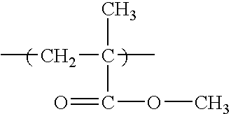
[0110]Thermoplastic resin 2: Acry pet VH (a product of Mitsubishi Rayon Co., Ltd., acryl resin)

[0111]Inorganic particle 5: HM-30S (silica particle made by Tokuyama Corp. primary particle size of 7 nm).

[0112]Meanwhile, as an inorganic particle 5, an inorganic particle in which HM...

embodiment 3

[0118]Using the above kneaded materials 1-11, plastic optical elements 1 to 11 (the numeral of the ending portion of “optical element 1-11” are related to the kneaded material 1-11.) were produced and evaluated. As the results, it was confirmed that optical elements 1, 4, 5, 7, 9 and 11 has a preferable optical properties and is superior in material deterioration resistance such as white turbidity when they are irradiated by blue-ray used for recording and reproduction of compact disc or digital versatile disk.


PUM

PropertyMeasurementUnit
Percent by massaaaaaaaaaa
Particle sizeaaaaaaaaaa

Abstract

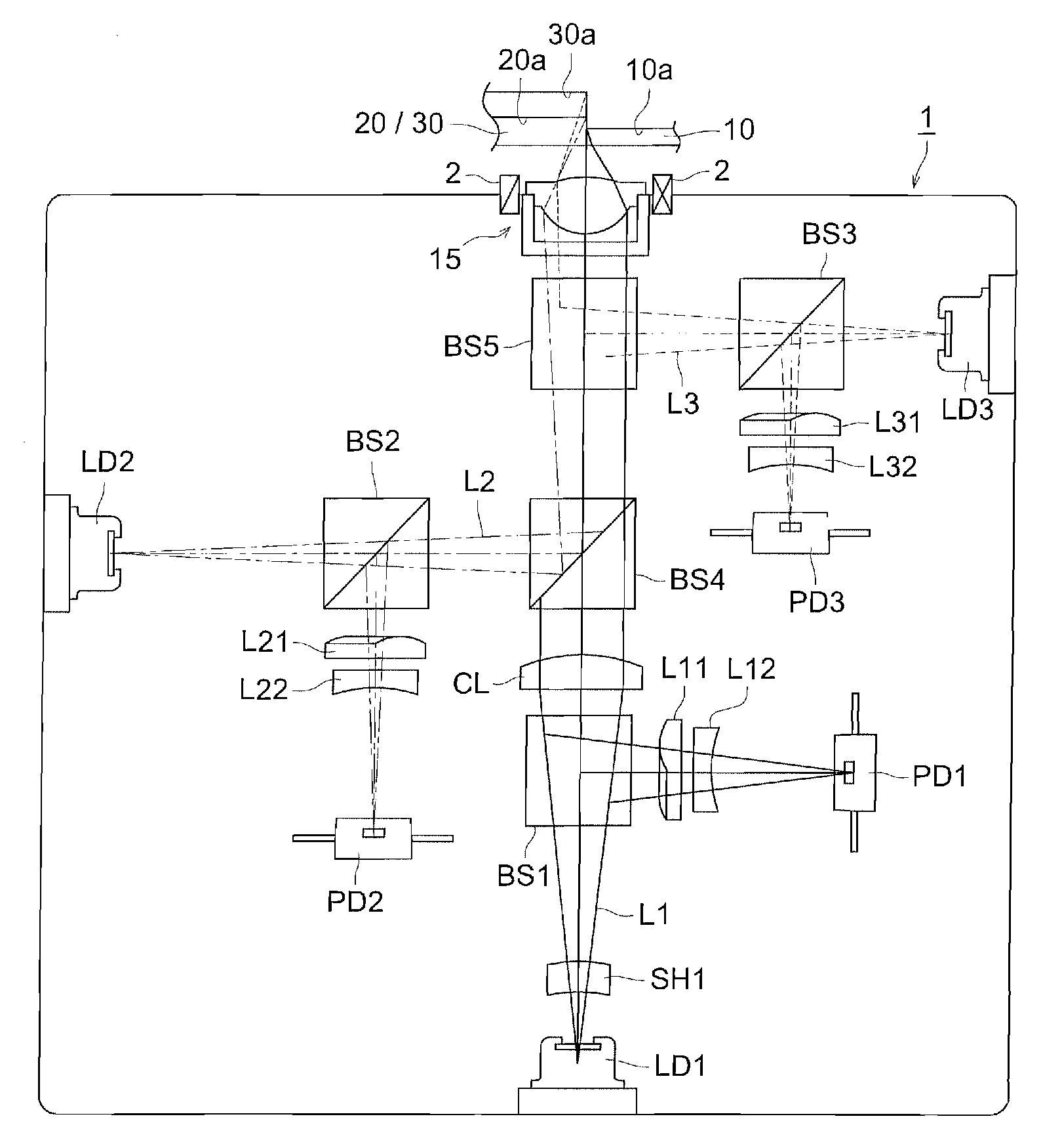
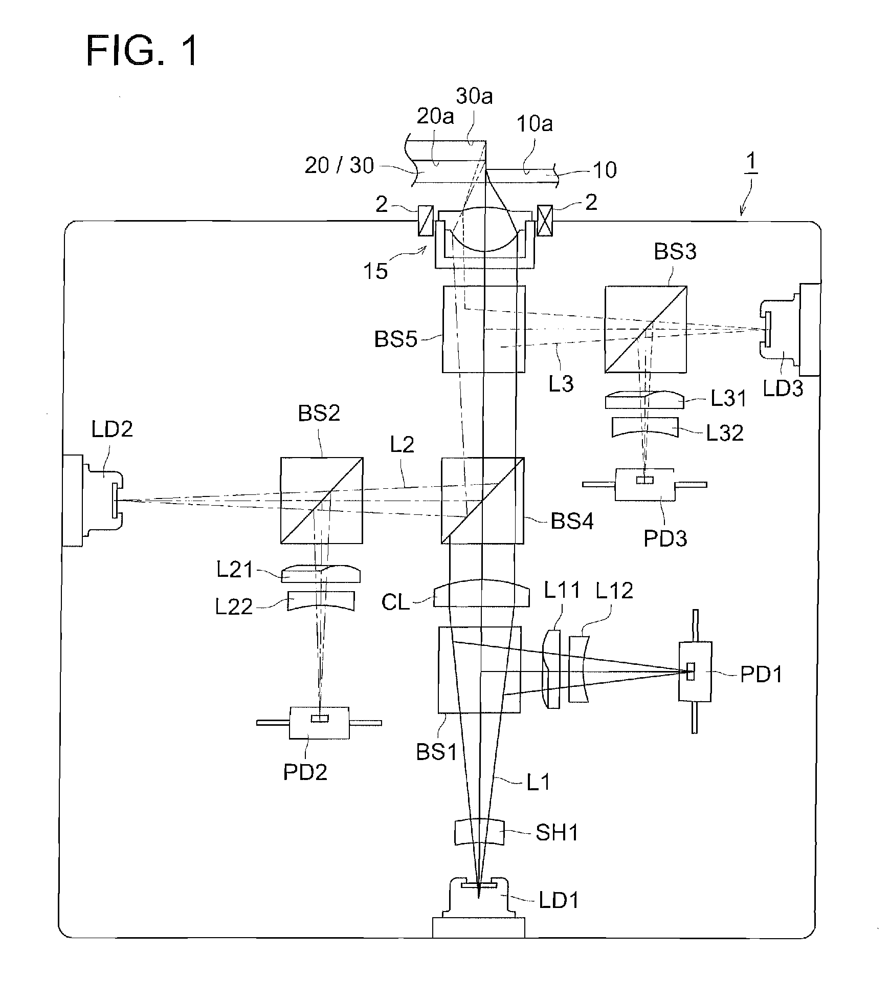
The present invention provides a transparent optical element having low thermal expansion and a manufacturing method of an optical element such as an object lens 15, the method having a melt-kneading process where a thermoplastic resin and an organic particle whose primary particles have a volume average dispersed particle size of not more than 30 nm, are melt-kneaded in an inert gas atmosphere.

Description

TECHNICAL FIELD[0001]The present invention relates to a manufacturing method of a thermoplastic composite material superior in transparency of a blue ray, preferably used for a lens, a filter, a grating, a optical fiber and a flat plate optical waveguide and the thermoplastic composite material and an optical element manufactured by the method thereof.BACKGROUND[0002]An optical pickup device is provided for a player, a recorder and a drive which read and record information on optical information recording media (hereinafter may simply called medium) such as MO, CD and DVD. The optical pickup device has an optical element unit which radiates a light beam having a predetermined wavelength from a light source on the medium and receives the reflected light beam by a light receiving element. The optical element unit has an optical element such as a lens which focuses the light beams on a reflecting layer of the medium or the light receiving element.[0003]For the optical element of the op...

Claims


Application Information

Patent Timeline
IPC IPC(8): C08L25/02B01F7/00
CPCB29B7/88B29C2791/005B29L2011/0016G02B7/008C08J2365/00G02B1/04C08J3/201
Inventor ANDO, HIROAKI
Owner KONICA MINOLTA OPTO
Learn More