
Radiographic apparatus and radiographic system

Inactive Publication Date: 2012-06-07
FUJIFILM CORP
View PDF11 Cites 22 Cited by
  • Summary
  • Abstract
  • Description
  • Claims
  • Application Information

AI Technical Summary

Benefits of technology

[0017]An object of the invention is to provide a radiographic apparatus and a radiographic system capable of sufficiently suppressing the thermal expansion of a multi-slit and enabling a favorable capturing of a phase contrast image.
[0020]According to the radiographic apparatus and the radiographic system, it is possible to sufficiently suppress the thermal expansion of the multi-slit and to enable a favorable capturing of a phase contrast image.

Problems solved by technology

However, the smaller the atomic number of the element configuring material, the X-ray absorption ability is reduced.
Accordingly, for the soft biological tissue or soft material, it is not possible to acquire the contrast of an image that is enough for the X-ray absorption image.
Thus, since a difference of the X-ray absorption amounts thereof is small, it is difficult to obtain the shading difference.
However, it takes several tens of minutes to perform the imaging and the resolution of the image is low such as about 1 mm.
Hence, it is difficult to use the MRI in a regular physical examination such as medical checkup due to the cost-effectiveness.
However, since the facility is too huge, it cannot be used in a usual hospital.
However, Patent Document 2 (WO-A-2008 / 102598 corresponding to US-A-2010 / 0080436) does not consider the thermal distortion of the multi-slit.
That is, the grating pitch of the multi-slit, the distance between the multi-slit and the first grating, the distance between the first and second gratings and the grating pitch of the second grating are geometrically determined and the quality of the phase contrast image is deteriorated when the determined corresponding relations become inappropriate.
Thereby, the quality of the phase contrast image is remarkably deteriorated.

Method used


Image

  • Radiographic apparatus and radiographic system
  • Radiographic apparatus and radiographic system
  • Radiographic apparatus and radiographic system

Examples


Embodiment Construction

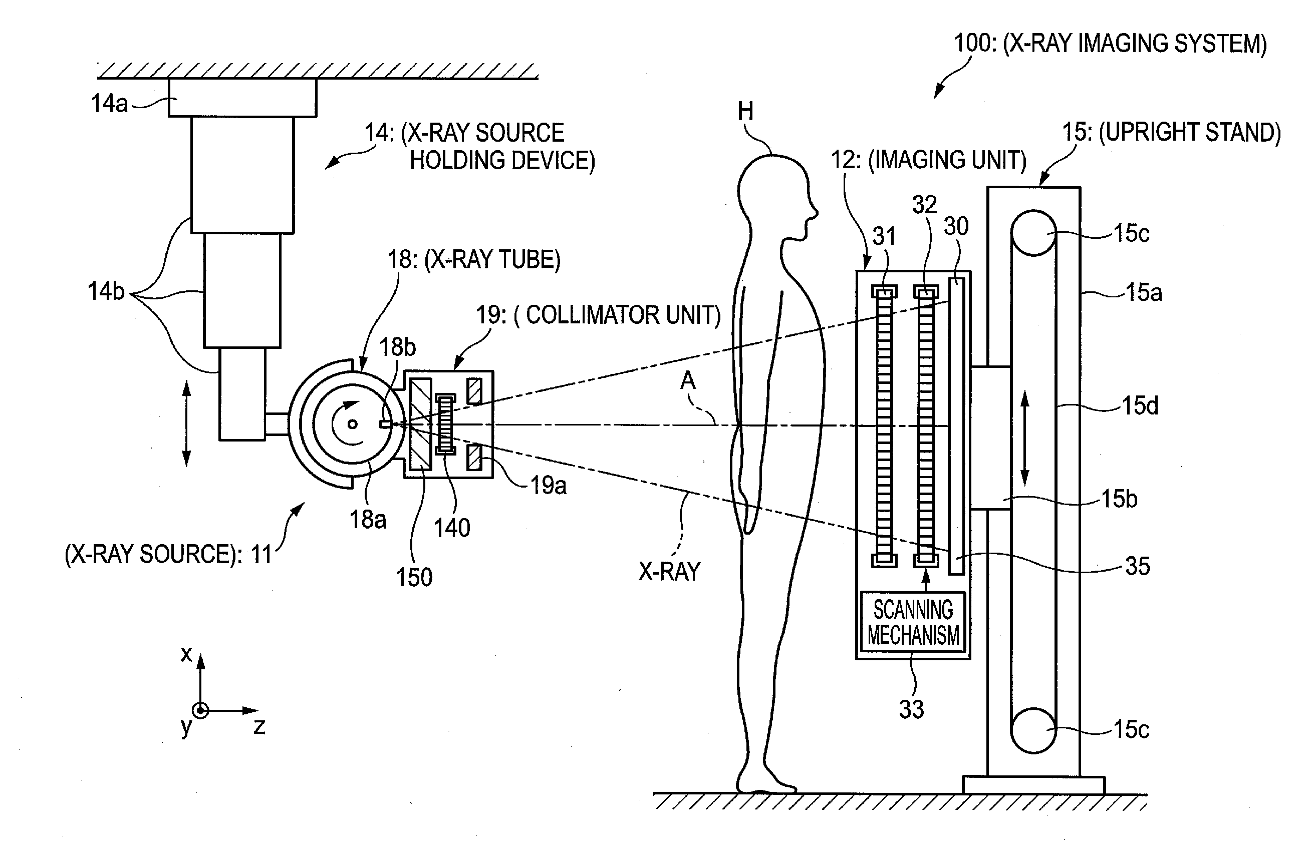
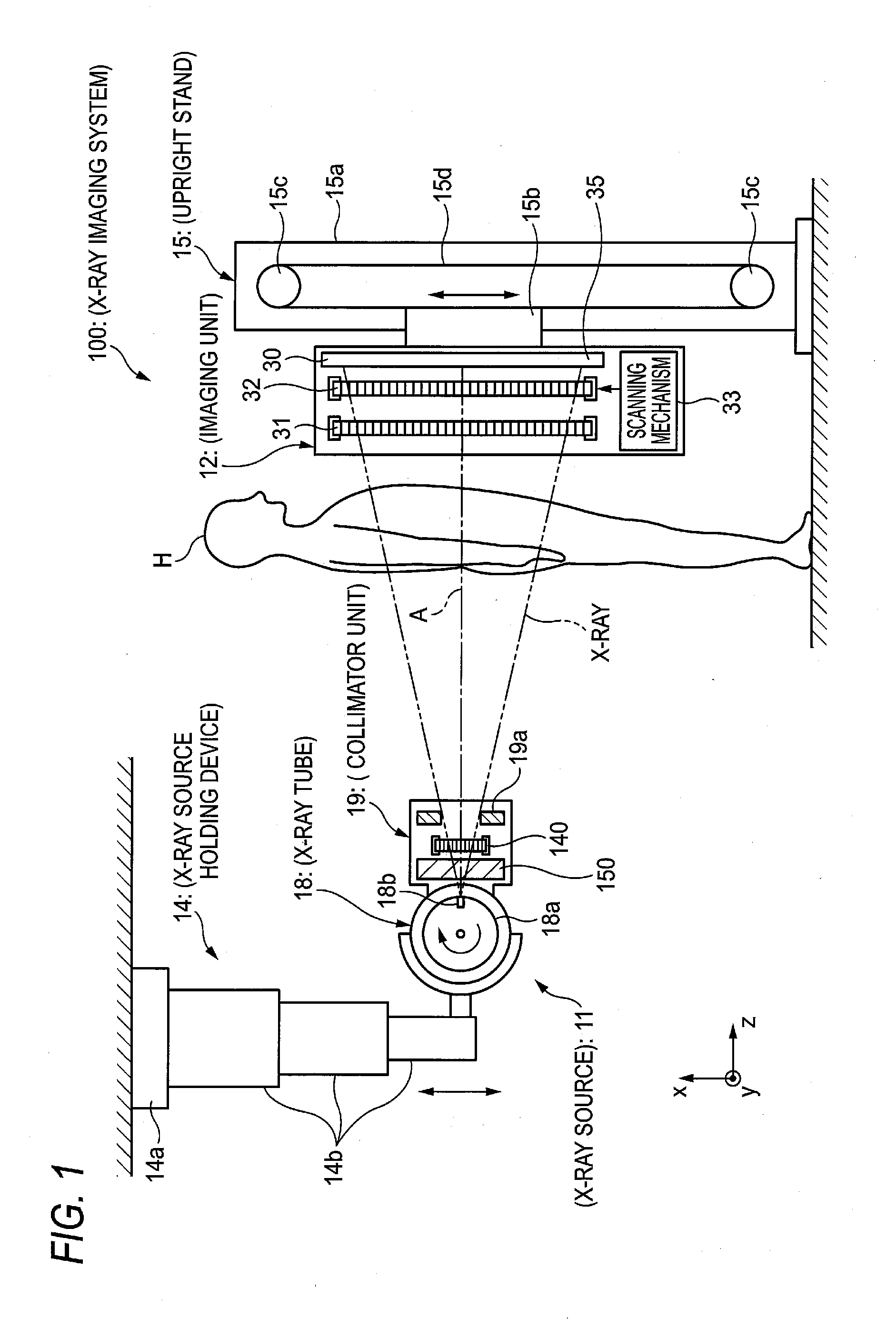
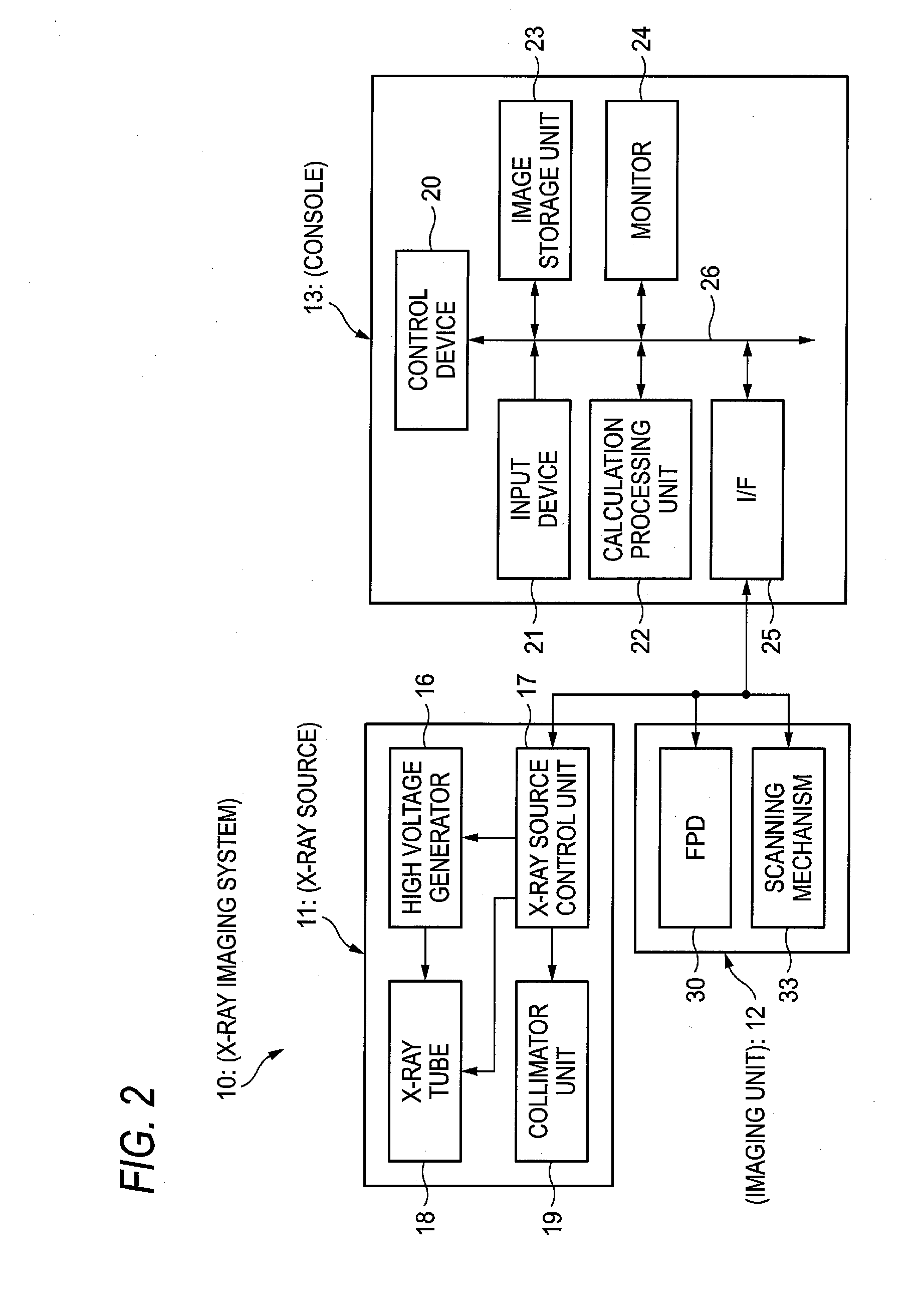
[0066]FIG. 1 shows an example of a configuration of a radiographic system for illustrating an illustrative embodiment of the invention and FIG. 2 is a control block diagram of the radiographic system of FIG. 1.

[0067]An X-ray imaging system 10 is an X-ray diagnosis apparatus that performs an imaging while a photographic subject (patient) H stands, and includes an X-ray source 11 that X-radiates the photographic subject H, an imaging unit 12 that is opposed to the X-ray source 11 with the photographic subject H being interposed between the X-ray source 11 and the imaging unit, detects the X-ray having penetrated the photographic subject H from the X-ray source 11 and thus generates image data and a console 13 (refer to FIG. 2) that controls an exposing operation of the X-ray source 11 and an imaging operation of the imaging unit 12 based on an operation of an operator, calculates the image data acquired by the imaging unit 12 and thus generates a phase contrast image.

[0068]The X-ray s...


PUM


Abstract

A radiographic apparatus includes: a first grating; a grating pattern having a period that substantially coincides with a pattern period of a radiological image formed by radiation having passed through the first grating; a radiological image detector that detects the radiological image masked by the grating pattern, and a third grating that is arranged at a more forward location than the first grating in a traveling direction of the radiation incident onto the first grating and selectively shields an area to which the radiation is irradiated, thereby forming disperse radiation sources. A heat insulation member is arranged at a more forward location than the third grating in the traveling direction of the radiation.

Description

CROSS-REFERENCE TO RELATED APPLICATIONS[0001]This application is based on and claims priority under 35 USC 119 from Japanese Patent Application No. 2010-273067 filed on Dec. 7, 2010, the entire content of which is incorporated herein by reference.BACKGROUND[0002]1. Technical Field[0003]The invention relates to a radiographic apparatus performing a phase imaging by radiation such as X-ray for a photographic subject and a radiographic system.[0004]2. Related Art[0005]Since X-ray attenuates depending on an atomic number of an element configuring a material and a density and a thickness of the material, it is used as a probe for seeing through an inside of a photographic subject. An imaging using the X-ray is widely spread in fields of medical diagnosis, nondestructive inspection and the like.[0006]In a general X-ray imaging system, a photographic subject is arranged between an X-ray source that irradiates the X-ray and an X-ray image detector that detects the X-ray, and a transmission ...

Claims


Application Information

Patent Timeline
IPC IPC(8): G01N23/04
CPCA61B6/4233A61B6/4441A61B6/4291A61B6/4464A61B6/484A61B6/4452
Inventor IWAKIRI, NAOTOMURAKOSHI, DAI
Owner FUJIFILM CORP
Learn More