Transform coder and transform coding method

Active Publication Date: 2009-11-12
III HLDG 12 LLC
View PDF35 Cites 41 Cited by
  • Summary
  • Abstract
  • Description
  • Claims
  • Application Information

AI Technical Summary

Benefits of technology

[0013]The present invention is able to reduce perceptual sp

Problems solved by technology

For this reason, the influence of scale factors upon subjective quality (i.e. human perceptual quality) is si

Method used


Image

  • Transform coder and transform coding method
  • Transform coder and transform coding method
  • Transform coder and transform coding method

Examples


embodiment 1

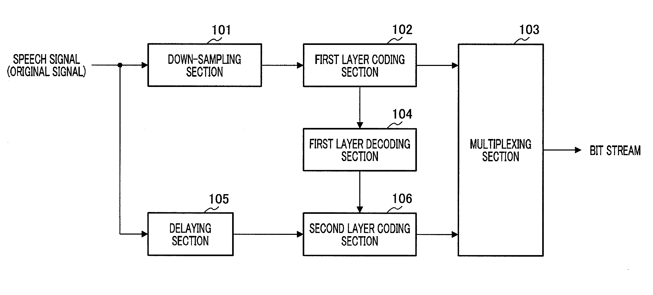
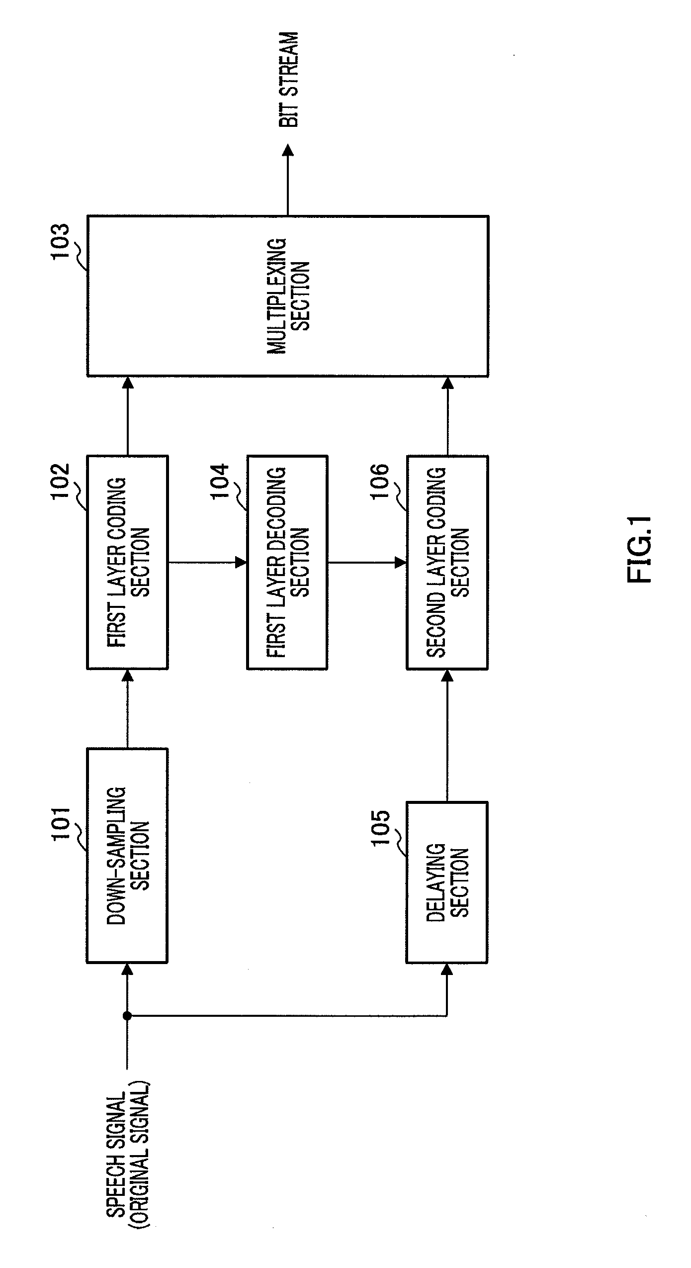
[0042]FIG. 1 is a block diagram showing the main configuration of a scalable coding apparatus having a transform coding apparatus according to Embodiment 1 of the present invention.

[0043]The scalable coding apparatus according to this embodiment has down-sampling section 101, first layer coding section 102, multiplexing section 103, first layer decoding section 104, delaying section 105 and second layer coding section 106, and these sections carry out the following operations.

[0044]Down-sampling section 101 generates a signal of sampling rate F1 (F1≦F2) from an input signal of sampling rate F2, and outputs the signal to first layer coding section 102. First layer coding section 102 encodes the signal of sampling rate F1 outputted from down-sampling section 101. The coding parameters obtained at first layer coding section 102 are given to multiplexing section 103 and to first layer decoding section104. First layer decoding section 104 generates a first layer decoded signal from codin...

embodiment 2

[0084]The basic configuration of the scalable coding apparatus that has the transform coding apparatus according to Embodiment 2 of the present invention is the same as in Embodiment 1. For this reason, repetition of description will be omitted here, and second layer coding section 206, which has a different configuration from Embodiment 1, will be described below.

[0085]FIG. 6 is a block diagram showing the main configuration inside second layer coding section 206. Second layer coding section 206 has the same basic configuration as second layer coding section 106 described in Embodiment 1, and so the same components will be assigned the same reference numerals and repetition of description will be omitted. Further, the basic operation is the same, but components having differences in details will be assigned the same reference numerals with small alphabet letters and will be described as appropriate. Furthermore, when other components are described, the same representation will be e...

embodiment 3

[0097]The basic configuration of the scalable coding apparatus that has the transform coding apparatus according to Embodiment 3 of the present invention is the same as in Embodiment 1. For this reason, repetition of description will be omitted and second layer coding section 306 that has a different configuration from Embodiment 1 will be described.

[0098]The basic operation of second layer coding section 306 is similar to the operation of second layer coding section 206 described in Embodiment 2 and differs in using the similarity, described later, instead of bit allocation information used in Embodiment 2. FIG. 8 is a block diagram showing the main configuration inside second layer coding section 306.

[0099]Similarity calculating section 311 calculates the similarity between a second spectrum of a signal band FL to FH, that is, the spectrum of the original signal and an estimated spectrum of a signal band FL to FH, and outputs the obtained similarity to correcting scale factor codi...


PUM


Abstract

A transform coder leading to reduction of degradation of perceptual sound quality even if an adequate number of bits is not assigned. Candidates of a correction scale factor stored in a correction scale factor codebook (123) are outputted one by one, and an error signal is generated by subjecting the candidate and scale factors outputted from scale factor computing sections (121, 122) to a predetermined operation. A judging section (126) determines a weight vector given to a weighted error computing section (127) depending on the sign of the error signal. The weighted error computing section (127) computes the square of the error signal, multiplies the square of the error signal by the weight vector given from the judging section (126), and computes a weighted squared error E. A search section (128) determines the candidates of the correction scale factor which minimizes the weighted squared error E by a closed loop processing.

Description

TECHNICAL FIELD[0001]The present invention relates to a transform coding apparatus and transform coding method for encoding input signals in the frequency domain.BACKGROUND ART[0002]A mobile communication system is required to compress speech signals in low bit rates for effective use of radio resources. Further, improvement of communication speech quality and realization of a communication service of high actuality are demanded. To meet these demands, it is preferable to make quality of speech signals high and encode signals other than speech signals, such as audio signals in wider bands, with high quality. For this reason, a technique of integrating a plurality of coding techniques in layers is regarded as promising.[0003]For example, this technique refers to integrating in layers the first layer where input signals according to models suitable for speech signals are encoded at low bit rates and the second layer where error signals between input signals and first layer decoded sig...

Claims


Application Information

Patent Timeline
IPC IPC(8): G10L19/00G10L19/02G10L19/035G10L19/038G10L19/16G10L19/20G10L19/26
CPCG10L19/0208G10L19/24G10L19/038G10L19/06
Inventor OSHIKIRI, MASAHIROYAMANASHI, TOMOFUMI
Owner III HLDG 12 LLC
Why Eureka
Try Eureka