Method of forming spring washer blind-holes into a piston for an automobile transmission

a technology of automobile transmission and blind-hole, which is applied in the direction of wheels, transportation and packaging, other domestic objects, etc., can solve the problems of insufficient forging technology, insufficient forging, and insufficient forging, so as to achieve sufficient pin endurance, avoid unnecessary load, and improve the effect of forging efficiency

Inactive Publication Date: 2009-11-19
IBARAKI STEEL CENT +1
View PDF4 Cites 8 Cited by
  • Summary
  • Abstract
  • Description
  • Claims
  • Application Information

AI Technical Summary

Benefits of technology

[0027]According to the first aspect of the present invention, the method of forming spring seat blind-holes into a piston for an automobile transmission, after forging the piston body with a flattened surface on which spring seat blind-holes are disposed, a plurality of spring seat blind-holes are formed at an extremely high speed by one stroke of extrusion operation of pins for piercing spring seat blind-holes. Since the piercing of the spring seat blind-holes is performed, as above, after having flattered an annular region of the piston body where the spring seat blind-holes are formed, unnecessary load will not be burdened on the pins for piercing spring seat blind-holes leading to sufficiently long endurance of the pins. Besides, a plurality of spring seat blind-holes concerned can be accommodated obviously to all of the cases where they are disposed at an equal angular distance; where a part of them are partially disposed at an equal angular distance; and where all of them are disposed at random.
[0028]Further, since the piercing of the spring seat blind-holes is performed by a forward extrusion operation with pins for piercing spring seat blind-holes. Therefore, since, naturally by any means using the die, flow of material is prevented out of the site for relief of material in front of the site where spring seat blind-holes are pierced, unnecessary deformation of the piston body into which spring seat blind-holes are formed will not occur.
[0029]According to the second aspect of the present invention, the method of forming spring seat blind-holes into a piston for an automobile transmission, the annular region along the back side peripheral edge of the end plate of the piston body can be flattered during forging the piston body of a piston for an automobile transmission without requiring a particular process for the flattering. Moreover, it is convenient that the process of forging the piston body is not especially complicated but a process which can be simply performed. Although there are many processes except the process above for flattening said region, flattening by the process mentioned above is extremely efficient because the flattening process is completed during the process of simple forging operation on the piston body.
[0030]Accordin

Problems solved by technology

At the moment, it seems that the method of forming spring washer blind-holes of a piston for an automobile transmission through forging technology has not been proposed yet.
The operations above are very inefficient, and moreover, subsequent endmilling operations in the same number as the drilling operations are also necessary and more inefficient in cost.
However, the proposal has not solved such inefficiency that extra parts should be employed and that drilling

Method used


Image

  • Method of forming spring washer blind-holes into a piston for an automobile transmission
  • Method of forming spring washer blind-holes into a piston for an automobile transmission
  • Method of forming spring washer blind-holes into a piston for an automobile transmission

Examples


Embodiment Construction

[0045]Most preferable mode for carrying out the present invention will be explained referring to the drawings on the basis of the example.

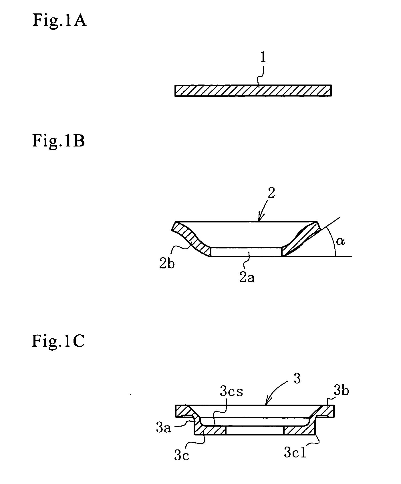
[0046]In the present example, as shown in FIG. 1A, a blank 1 was formed by cutting a disc 105 mm in outer diameter out of S25C steel plate 9.0 mm thick. After being descaled by shot blasting, it was treated by so-called Bonde treating consisting of solid lubricant (phosphate). Additionally, although S25C steel plate was used to form disc-like blank 1 in the example as above, SAE1020, SAE 1018, or other equivalents can be employed in place of it as you like.

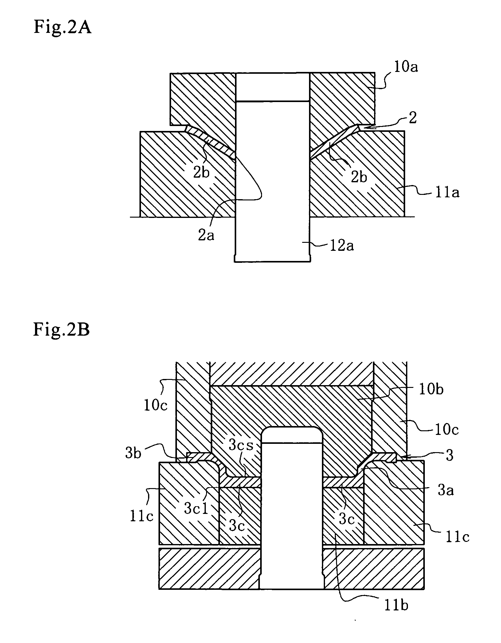
[0047]Then, as shown in FIG. 1B and FIG. 2A, a center-hole 12a was punched out in the shape of a circle in the center of the disk-like blank 1 with a punch for blanking, and simultaneously a peripheral of the center-hole 2a was formed into a circumferential sidewall 2b rising oblique by deep-drawing with an upper die 10a and a lower die 11a to thereby forge a primary workpiece 2. The reason why ...


PUM

PropertyMeasurementUnit
Fractionaaaaaaaaaa
Fractionaaaaaaaaaa
Massaaaaaaaaaa

Abstract

The problem to be solved by the present invention is to clear up an eccentric load onto a pin and a problem of deformation and cavity due to flowing material during extrusion when spring washer blind-holes in a piston for an automobile transmission is formed by extrusion with a pin. After an annular region along the peripheral edge portion on the back of an end plate 3c of a secondary workpiece 3 is flattened, the secondary workpiece 3 is set on a lower die 11f. Further, while the lower die is pressed with upper dies 10f, 10g and cushion pressure is applied on the lower die 11f, pins 13, 13 . . . for piercing the spring washer blind-holes are made to perform an extrusion operation onto the end plate 3c of the secondary workpiece 3 from the backside of said end plate. The extruded material is made to flow into recess holes 10f1, 10f1 . . . of the upper die 10f and thus spring washer blind-holes 5, 5 . . . are formed. Then, projections 3cp which have flowed and protruded on the front side are removed by turning with a lathe.

Description

TECHNICAL FIELD[0001]The present invention relates to a method of forming spring washer(seat) blind-holes of a piston for an automobile transmission, wherein a plurality of spring washer blind-holes on the back of an end plate of the piston for the automobile transmission are formed efficiently, keeping endurance of pins for piercing the spring washer blind-holes, and precisely by cold forging.BACKGROUND ART[0002]At the moment, it seems that the method of forming spring washer blind-holes of a piston for an automobile transmission through forging technology has not been proposed yet.[0003]For example, it is shown in Patent Document 1 that spring washer blind-holes (they are simply referred as recesses in the document) are disposed on the inner surface of the end plate of the piston in a multiple-disc clutch, however there is no comment upon the method of forming them.[0004]With regard to the method of manufacturing oil hydraulic machine parts in Patent Document 2, a combined method ...

Claims


Application Information

Patent Timeline
IPC IPC(8): B21C23/00
CPCB21J5/02B21K23/00B21K1/32B21K1/18
Inventor OOKA, MASAKAZUHIYAMA, YOSHIKITANABE, KENTAROKANZAKI, YOSHIYUKISATO, SATOSHIYAMAZAKI, YOSHIHISAGOTO, KIICHIRO
Owner IBARAKI STEEL CENT
Why Eureka
Try Eureka