Metal-top welding table

a welding table and metal top technology, applied in the direction of variable height tables, soldering devices, auxillary welding devices, etc., can solve the problem of unadjustable flanges, etc., and achieve the effect of increasing flexibility and convenience, easy storage and portability, and increasing the strength of the table top

Inactive Publication Date: 2009-11-19
WONG HARRY
View PDF23 Cites 85 Cited by
  • Summary
  • Abstract
  • Description
  • Claims
  • Application Information

AI Technical Summary

Benefits of technology

[0006]The rectangular flat table top is made of sheet metal for rigidity without adding too much weight to the present invention. The four edges of the table top are bent downward to form four fold-down edges. At proper location of the flat table top, a plurality of elongated slots are equipped for the insertion of clamping tools. Elongated slots accepts clamping tools with cylindrical shanks as well as most other types of clamping tools, say C-clamps, bar clamps, etc. This will increase the flexibility and convenience of the present invention. The straight edge of each elongated slot is bent downward to a proper depth to increase the strength of the table top and to create a thickness of the table top for clamping tool usage.
[0007]At least one fold-down edge of the table top is made with two or more screw holes for the mounting of the angle flange. The angle flange is equipped with two or more elongated holes on one side for mounting to one of the fold-down edge of the table top with wing screws. The angle flange is equipped with one or more elongated slots on the other side for the mounting of additional clamping tool if necessary. The position of the angle flange relative to the table top is adjustable so that the upper edge of the angle flange is below the table top or protrude above the table top. The amount of protrusion is variable utilizing the elongated holes on the angle flange and the wing screws. When the upper edge of the angle flange protrudes above the table top, workpiece can be held against the angle flange by clamping tool. When adjacent fold-down edges of the table top are equipped with angle flanges, then the two protruded adjacent angle flanges form a right angle guide rail to align two workpieces at 90 degree spatial relationship easily. At least one V-notch is formed on the upper edge of the angle flange to hold cylindrical or bar shape workpiece firmly and easily on the table top. This feature adds more flexibility to the present invention.
[0008]The flat table top is mounted on a support structure which comprises two straight shanks, two semicircular plates with semicircular slots, and ...

Problems solved by technology

Some prior arts equipped with flanges to hol...

Method used


Image

  • Metal-top welding table
  • Metal-top welding table
  • Metal-top welding table

Examples


Embodiment Construction

[0019]With the help of the drawings and the detail description below, the features of the present invention will be apparent and fully understandable.

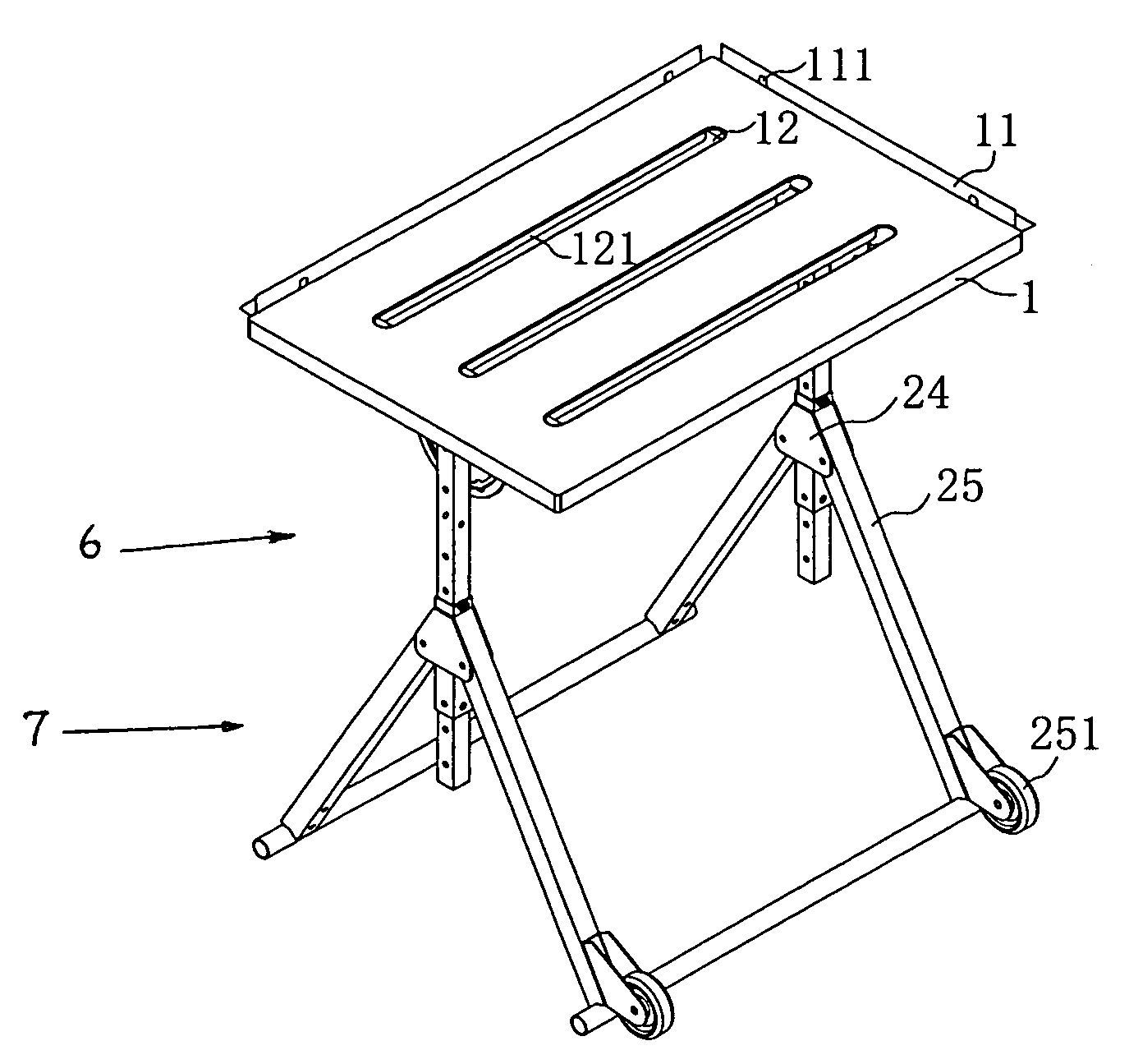
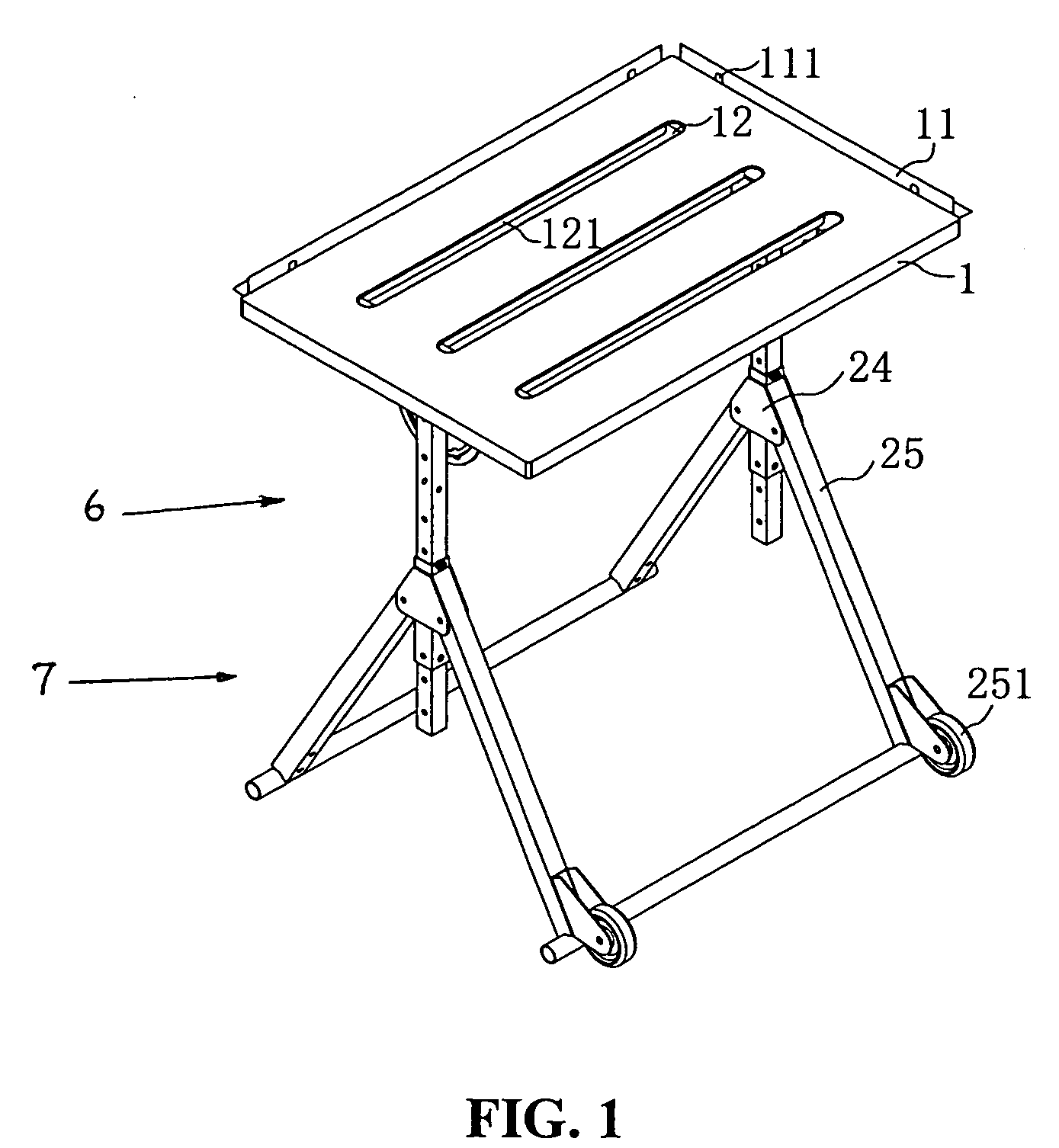
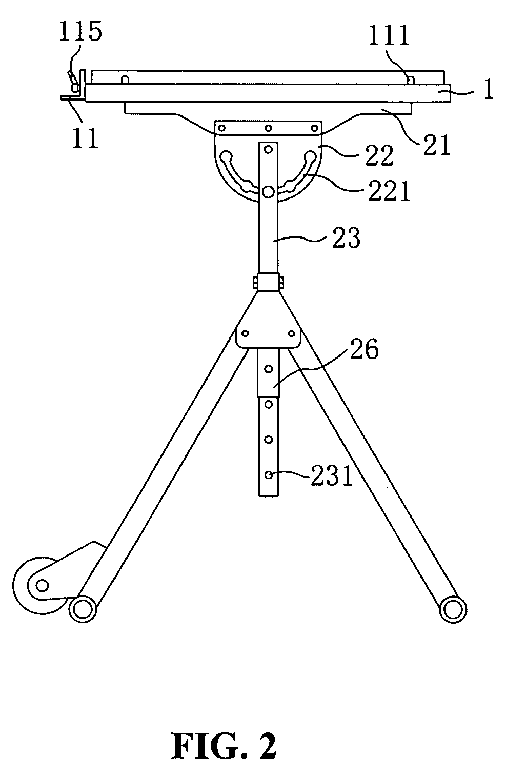
[0020]Referring to FIG. 1, the present invention comprises a rectangular flat table top 1 with protrusion-adjustable angle flange 11 and elongated slots 12, a support structure 6 having an angle and height adjusting mechanism, and a foldable base frame 7 with casters 251.

[0021]Referring to FIG. 7, FIG. 8 and FIG. 9, the flat table top 1 is made of sheet metal for rigidity without adding too much weight on the present invention. At proper location of the flat table top 1, a plurality of elongated slots 12 are equipped for the insertion of clamping tools with cylindrical shanks as well as other types of clamping tools such as C-clamps, bar clamps, etc. Cylindrical tool holes on table top cannot accept C-clamps or bar clamps. The straight edge 121 of each elongated slot is bent downward to a proper depth to form a thickness of the table t...


PUM


Abstract

A welding table used in welding industry and woodworking applications comprises a metal table top with retractable carrying handle and elongated slots for insertion of clamping tools, a protrusion-adjustable angle flange with V-notch mounted to at least one edge of the table top, a support structure having an angle and height adjusting mechanism, and a foldable base frame with casters.

Description

BACKGROUND OF THE INVENTION[0001]1. Field of the Invention[0002]The present invention relates to a class of portable workbench in general, and particularly to a metal-top welding table used in welding industry and woodworking applications. The present invention comprises a metal table top with retractable carrying handle and elongated slots for insertion of clamping tools, a protrusion-adjustable angle flange with V-notch mounted to at least one edge of the table top, a support structure having an angle and height adjusting mechanism, and a foldable base frame with casters.[0003]2. Description of the Related Art[0004]A portable workbench used in welding industry and woodworking applications typically comprises a flat table top with a number of round holes for inserting clamping tools. The flat table top is either made of plastic material to reduce the weight for portability in the expense of strength and rigidity or made of heavy solid metal plates for rigidity but too heavy for por...

Claims


Application Information

Patent Timeline
IPC IPC(8): A47B9/06A47B3/083
CPCB23K37/0461B25H1/18B25H1/16B25H1/04
Inventor WONG, HARRY
Owner WONG HARRY
Why Eureka
Try Eureka