Reinforcing bar binding machine

a technology of reinforcing bars and binding machines, which is applied in the directions of bundling articles, bundling machine details, transportation and packaging, etc., can solve the problems of large-sized fixing tools that cannot be used, set screws b>53/b> easily loosening during repeated use, and grease becomes insufficient in some cases, so as to reduce size and weight, the effect of reducing the size and weigh

Active Publication Date: 2009-11-19
MAX CO LTD
View PDF4 Cites 12 Cited by
  • Summary
  • Abstract
  • Description
  • Claims
  • Application Information

AI Technical Summary

Benefits of technology

[0012]One or more embodiments of the invention provide a reinforcing bar binding machine including a binding de

Problems solved by technology

A load is transmitted from the inner sleeve to the outer sleeve via the set screw 53, however, downsizing takes precedence, so that a large-sized fixing tool cannot be used, and the set screw 53 easily loosens during repeated use.
Normally, between the sleeve and these members, grease is applied, so that the frictional force is maintained small, however, the grease becomes insufficient in some cases.
In these cases, the lubricating function is deteriorated and the frictional force between the sleeve and the members increase, and a phenomenon easily occurs in which the sleeve cannot

Method used


Image

  • Reinforcing bar binding machine
  • Reinforcing bar binding machine
  • Reinforcing bar binding machine

Examples


Embodiment Construction

[0053]Exemplary embodiments of the invention are described in reference to drawings.

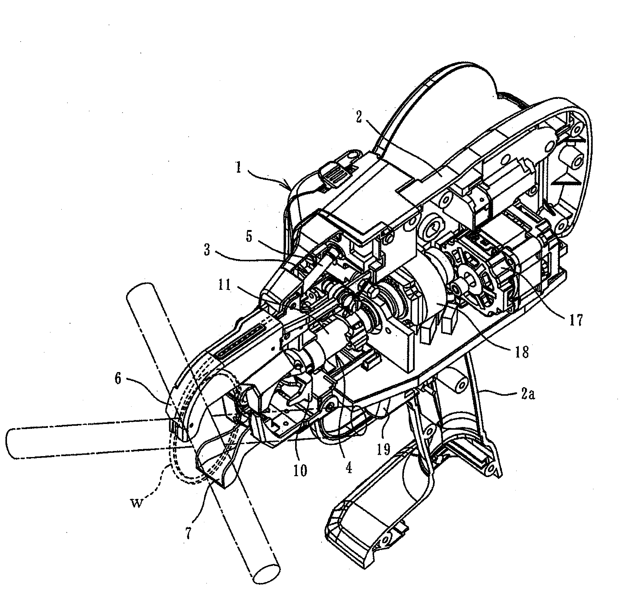
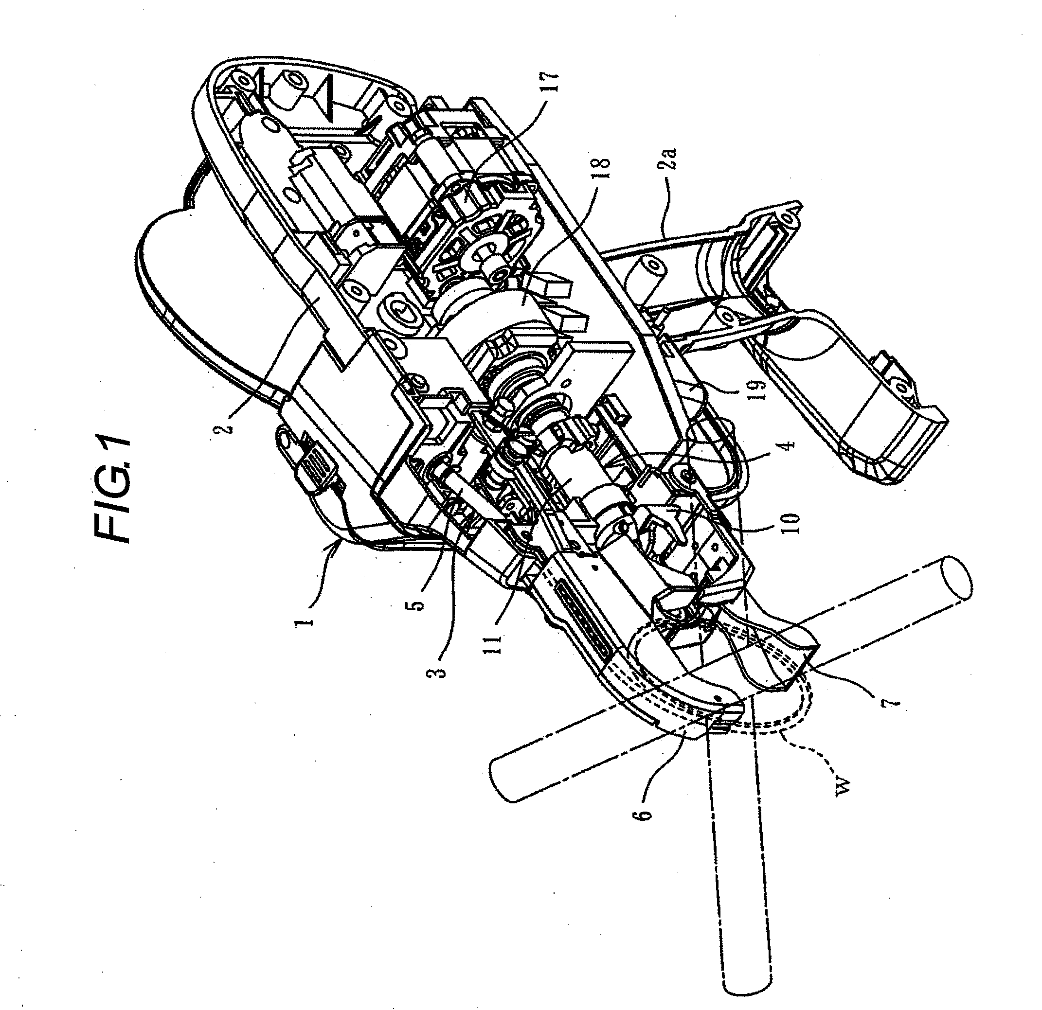
[0054]FIG. 1 is a perspective view showing an internal state of a reinforcing bar binding machine main body, and this reinforcing bar binding machine main body 1 includes a reinforcing bar binding wire feeding device 3 and a wire binding device 4 installed in a housing 2, and a wire reel (not shown) rotatably pivotally mounted to a rear side surface of the housing 2.

[0055]The wire feeding device 3 feeds a wire w wound around a wire reel from a guide tube 5 to a wire guide 6 by a feed roller not shown, and curls the wire here and loops and winds the wire around reinforcing bars (not shown) between the wire guide 6 and a lower guide 7, and the wire binding device 5 grasps and twists a part of the looped wire w to bind the reinforcing bars, and the terminal end portions of the loop of the wire w are cut during actuation of the binding device 4.

[0056]The wire feeding device 3 and the wire binding device ...


PUM

PropertyMeasurementUnit
Speedaaaaaaaaaa

Abstract

A reinforcing bar binding machine is provided with: a main sleeve having a tip end on which a hook is pivotally mounted; a tip end shaft fitted in an inside of the main sleeve; a spiral screw groove formed on the tip end shaft; a fitting opening that penetrates from an outside to the inside of the main sleeve; a key fitted in the fitting opening and brought in mash engagement with the screw groove; a short sleeve provided on an outer periphery of the main sleeve and covering the key; and an engaging means formed on the short sleeve and controlling a rotation of the main sleeve.

Description

BACKGROUND OF THE INVENTION[0001]1. Field of the Invention[0002]The present invention relates to a reinforcing bar binding machine including a binding device which binds arranged reinforcing bars by twisting a wire looped and wound around the reinforcing bars.[0003]2. Background Art[0004]In a reinforcing bar arrangement process of a reinforced concrete construction work, as a tool for binding reinforcing bars at a crossing point, etc., of reinforcing bars, a reinforcing bar binding machine is known. This reinforcing bar binding machine is provided with a binding device for binding reinforcing bars. As shown in JP-B2-3496463, this binding device includes a sleeve which is provided inside the binding machine body and has reinforcing bar binding hooks pivotally mounted to the tip end, a tip end shaft which is fitted to the inside of the sleeve and generates a load for advancing and retreating and rotating the sleeve, and engaging means (fins) for controlling the rotation of the sleeve ...

Claims


Application Information

Patent Timeline
IPC IPC(8): E04G21/12B21F15/04
CPCY10T29/5187E04G21/122B65B13/28E04G21/123
Inventor NAGAOKA, TAKAHIROKOBAYASHI, TSUYOSHI
Owner MAX CO LTD
Why Eureka
Try Eureka