Combined Vehicle Brake With Electromechanically Operable Parking Brake and Gear For Converting A Rotary Movement Into A Translational Movement

a technology of electric motor and parking brake, which is applied in the direction of gearing control, mechanical equipment, gearing control, etc., can solve the problems of relatively high manufacturing cost of the ball screw mechanism of the prior art, and achieve the effects of reducing electrical power consumption, high efficiency, and cost-effective manufacturing

Active Publication Date: 2009-11-19
CONTINENTAL TEVES AG & CO OHG
View PDF10 Cites 60 Cited by
  • Summary
  • Abstract
  • Description
  • Claims
  • Application Information

AI Technical Summary

Benefits of technology

[0006]An object of the present invention therefore is to improve a combined vehicle brake of the generic type specified in the introduction in such a way that the transmission of the electromechanically actuated parking brake is cost-effective to manufacture and at the same time has a high efficiency, in order to reduce the electrical power consumption for performing parking brake actions. A further object of the present invention is to describe such a transmission.

Problems solved by technology

This ball channel is costly to produce, which therefore makes a ball screw mechanism of prior art relatively expensive to manufacture.

Method used


Image

  • Combined Vehicle Brake With Electromechanically Operable Parking Brake and Gear For Converting A Rotary Movement Into A Translational Movement
  • Combined Vehicle Brake With Electromechanically Operable Parking Brake and Gear For Converting A Rotary Movement Into A Translational Movement
  • Combined Vehicle Brake With Electromechanically Operable Parking Brake and Gear For Converting A Rotary Movement Into A Translational Movement

Examples


first embodiment

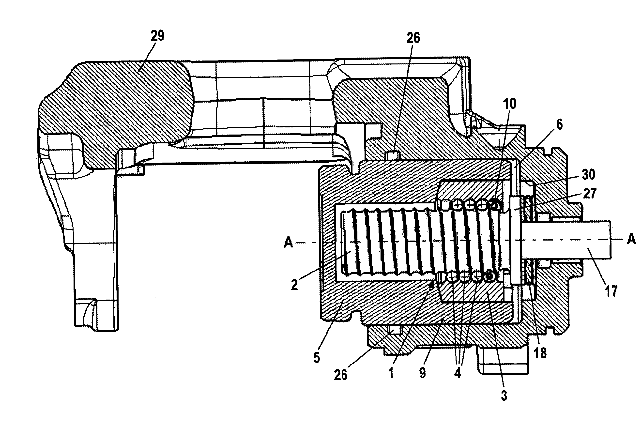
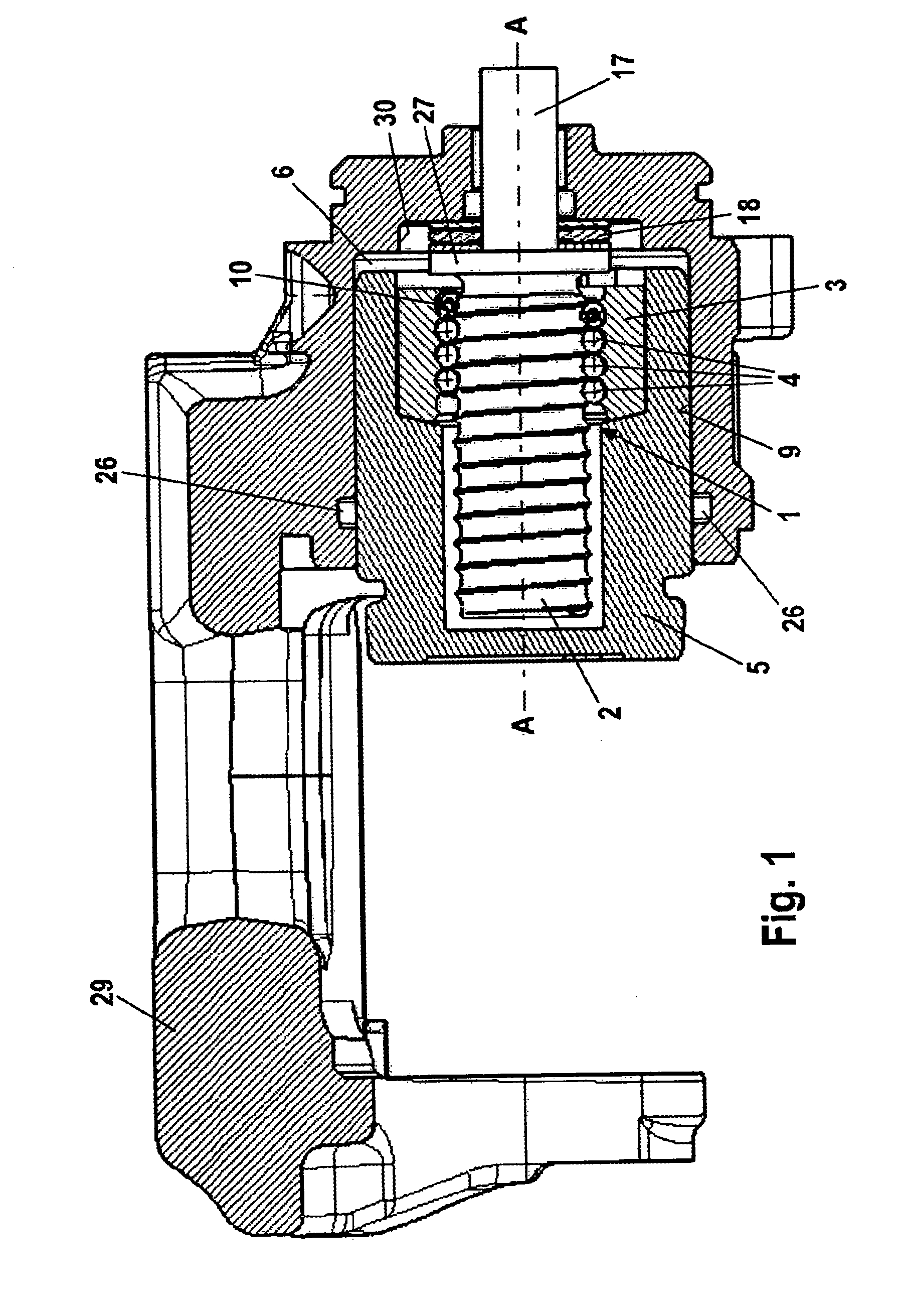
[0036]FIG. 3 represents the transmission 1. FIG. 3 shows that the balls 4 are arranged so that they can move to a limited extent between two stops 21, 22 in the thread between the screw spindle 2 and the screw nut 3. A spring element 10, which allows the balls 4 to slide in no-load actuation of the transmission 1 and allows the balls 4 to roll when the transmission 1 is actuated under load, is arranged between the first stop 21 and the balls 4, the spring element 10 acting as buffer and maintaining some rolling travel ahead of the balls. The stops 21, 22 are frictionally coupled to the spindle nut. Alternatively they may be integrally formed with the spindle nut.

second embodiment

[0037]the transmission 1 shown in FIG. 4 has a second spring 20, which is arranged between the second stop 22, not shown here, and the rolling elements 4. This additional second spring 20 serves as buffer when releasing the parking brake. This second spring element 20 comes into play if a high hydraulic brake pressure has been admitted into the operating pressure chamber 6 prior to actuation of the parking brake. In this case the rolling distance of the balls 4 when releasing the parking brake is greater than when actuating the parking brake and the second spring element 20 maintains a rolling travel ahead of the balls 4 as a buffer.

[0038]Both of the embodiments represented in FIGS. 3 and 4 have a screw spindle 2, the lead of which is between 3 mm and 5 mm per revolution. The spindle nut 3 preferably has 2 to 5 thread turns.

[0039]FIGS. 5a to 5d show an exemplary embodiment of the stops 21, 22 in FIGS. 3 and 4. As the two sectional representations in FIGS. 5b and 5d illustrate, the s...


PUM


Abstract

A combined vehicle brake including a hydraulically actuated service brake and an electromechanically actuated parking brake device, a hydraulic operating pressure chamber in a brake housing being defined by a brake piston, which for performing service braking actions can be acted upon by hydraulic pressure fluid, so that the brake piston can be actuated along a piston longitudinal axis in order to produce a braking action, and the parking brake device acting on the brake piston by way of a transmission that translates the rotary motion of an electromechanical actuator into a translational motion and actuates the brake piston to perform parking brake actions and to keep it in the actuated position. Also disclosed is a transmission for translating a rotary motion into a translational motion by way of a screw spindle and a spindle nut, which are in contact with one another by way of multiple rolling elements.

Description

CROSS REFERENCE TO RELATED APPLICATIONS[0001]This application is the U.S. national phase application of PCT International Application No. PCT / EP2007 / 060213, filed Sep. 26, 2007, which claims priority to German Patent Application No. DE102006045999.7, filed Sep. 27, 2006, German Patent Application No. DE102007002446.2, filed Jan. 11, 2007, German Patent Application No. DE102007017210.0, filed Apr. 12, 2007, German Patent Application No. DE102007036460.3, filed Aug. 1, 2007, and German Patent Application No. DE102007046180.3, filed Sep. 26, 2007, the contents of such applications being incorporated by reference herein.BACKGROUND OF THE INVENTION[0002]1. Field of the Invention[0003]The present invention relates to a combined vehicle brake, which comprises a hydraulically actuated service brake and an electromechanically actuated parking brake device a hydraulic operating pressure chamber in a brake housing being defined by a brake piston, which for performing service braking actions ca...

Claims


Application Information

Patent Timeline
Patent Type & Authority Applications(United States)
IPC IPC(8): F16D65/24F16H25/18F16D65/22F16D65/18
CPCF16D2125/40Y10T74/19181F16D65/18F16D2123/00F16H25/2233F16D2121/02F16D2121/24F16D65/14F16H25/22
Inventor WINKLER, THOMASBALZ, JURGENKOCH, DIRKSCHUMANN, MARCUSKLIMT, ANJABAUER, JURGENHINTZ, TORSTEN
Owner CONTINENTAL TEVES AG & CO OHG
Why Eureka
Try Eureka