Method and apparatus for estimating induction motor rotor temperature

a technology of induction motor and rotor temperature, which is applied in the direction of motor/generator/converter stopper, dynamo-electric converter control, instruments, etc., can solve the problems of rotor conductor burnout or even total motor failure, add operating cost to line-connected induction motors, and expensive methods of measurement. , to achieve the effect of adding cost and bulk to the motor

Inactive Publication Date: 2009-11-19
SQUARE D CO
View PDF2 Cites 33 Cited by
  • Summary
  • Abstract
  • Description
  • Claims
  • Application Information

AI Technical Summary

Benefits of technology

[0011]Second, an instantaneous rotor speed is detected by calculating the rotational speed of a single rotor slot harmonic component, which is extracted from the complex current space vector, with respect to the rotational speed of a fundamental frequency component, which is extracted from the complex voltage space vector. This rotor speed measurement / estimation eliminates the need for a speed measurement from a tachometer, which adds cost and bulk to the motor.

Problems solved by technology

The accumulation of excessive heat on the rotor of an induction motor can cause severe thermal stress to the rotor structure, resulting in rotor conductor burnout or even total motor failure.
These methods of measurement typically involve expensive instruments and dedicated wiring from the motors back to a motor control center.
Therefore, this approach adds operating cost to line-connected induction motors.
Consequently, such thermal models cannot respond to changes in the motors' cooling capability, such as a broken cooling fan or a clogged motor casing.
Therefore, this approach is incapable of giving an accurate estimate of the rotor temperature tailored to a specific motor's cooling capability.
However, this approach requires an injection circuit and is usually impractical for line-connected induction motors.
However, accurate rotor temperature cannot be reliably obtained during dynamic motor operations, where motors are connected to time-varying loads such as reciprocating compressors or pumps.
In addition, because most spectral estimation techniques require that the whole sequence of current samples, acquired at steady-state motor operation, be available for batch processing, such techniques can cause significant delay between the data acquisition and the final output of the temperature estimates.

Method used


Image

  • Method and apparatus for estimating induction motor rotor temperature
  • Method and apparatus for estimating induction motor rotor temperature
  • Method and apparatus for estimating induction motor rotor temperature

Examples


Embodiment Construction

[0039]Although the invention will be described in connection with certain aspects and / or embodiments, it will be understood that the invention is not limited to those particular aspects and / or embodiments. On the contrary, the invention is intended to cover all alternatives, modifications, and equivalent arrangements as may be included within the spirit and scope of the invention as defined by the appended claims.

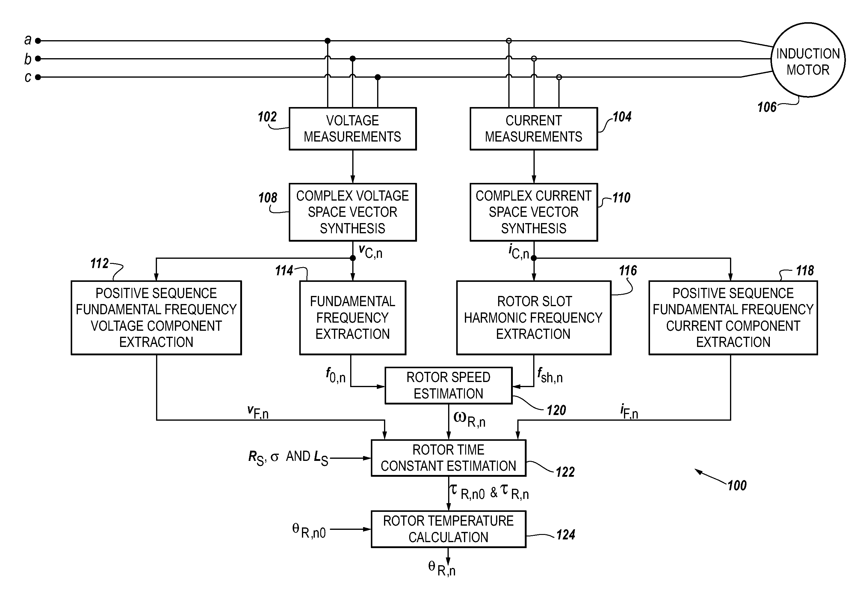
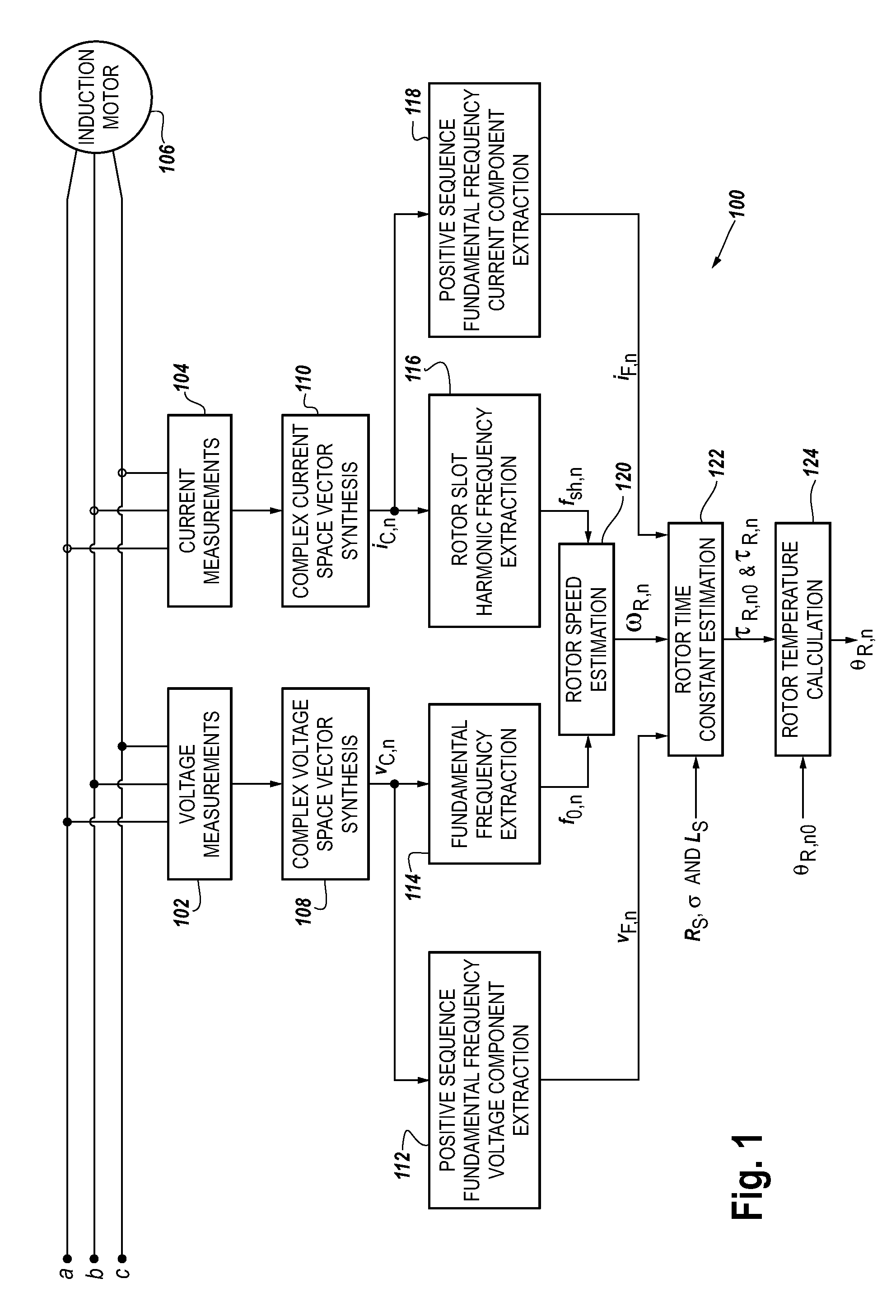
[0040]Referring to FIG. 1, an architecture (100) for estimating rotor temperature in an induction motor 106 is illustrated according to some aspects of the present concepts. The architecture (100) includes a complex voltage space vector synthesis (108), a complex current space vector synthesis (110), a rotor speed estimation (120), a positive sequence fundamental frequency voltage component extraction (112), a positive sequence fundamental frequency current component extraction (118), a rotor time constant estimation (122), and a rotor temperature calculation (124).

Complex ...


PUM


Abstract

A method and apparatus to provide continuous and reliable rotor temperature estimates for line-connected induction motors during steady-state and / or dynamic motor operations. Rotor temperature is calculated from voltage and current measurements without any temperature or speed sensors. First, complex space vectors are synthesized from voltage and current measurements. Second, the instantaneous rotor speed is detected by calculating the rotational speed of a single rotor slot harmonic component with respect to the rotational speed of the fundamental frequency component. Third, the positive sequence fundamental frequency components are extracted from complex space vectors. Fourth, the rotor time constant is estimated in a model-reference adaptive system based on a dynamic induction motor equivalent circuit model. Finally, the rotor temperature is calculated according to the linear relationship between the rotor temperature and the estimated rotor time constant. Real-time induction motor thermal protection is achieved through this continuous tracking of the rotor temperature.

Description

CROSS-REFERENCE TO RELATED APPLICATION[0001]This application claims the benefit of U.S. Provisional Application Ser. No. 61 / 053,941, filed May 16, 2008, entitled “Methods and Apparatuses for Estimating Transient Slip, Rotor Slots, Motor Parameters, and Induction Motor Temperature.”FIELD OF THE INVENTION[0002]The present disclosure relates generally to the estimation of rotor temperatures in induction motors without using actual temperature or speed sensors. More particularly, this disclosure relates to the continuous estimation of the rotor temperature from measurements of voltage and current, for motors operated at steady-state and / or dynamic conditions.BACKGROUND[0003]The accumulation of excessive heat on the rotor of an induction motor can cause severe thermal stress to the rotor structure, resulting in rotor conductor burnout or even total motor failure. Consequently, an accurate and reliable real-time tracking of the rotor temperature is needed to provide an adequate warning of...

Claims


Application Information

Patent Timeline
Patent Type & Authority Applications(United States)
IPC IPC(8): G01R27/08
CPCH02P21/145H02P21/16H02P23/14H02P2207/01H02P29/66
Inventor COLBY, ROY S.GAO, ZHITURNER, LARRY A.
Owner SQUARE D CO
Why Eureka
Try Eureka