Controllable device for phase modulation

a controllable device and phase modulation technology, applied in the direction of optics, holographic processes, holographic properties/properties, etc., can solve the problems of two phase conditions per modulator cell, the switching delay of less than 1 millisecond for ips lc slm is not achieved, and the simple modification of ips lc slm is not adequate, so as to achieve the effect of shortening the switching delay

Active Publication Date: 2009-11-19
SEEREAL TECHNOLOGIES
View PDF2 Cites 34 Cited by
  • Summary
  • Abstract
  • Description
  • Claims
  • Application Information

AI Technical Summary

Benefits of technology

[0023]Because the LC molecules mainly move in the plane of the modulator matrix, as mentioned in the description of the prior art, a similar behaviour must be expected as regards phase modulation as in an IPS LC SLM, but with the advantage that shorter switching delays are achieved.
[0024]An orientation of the LC molecules out of the plane of the modulator matrix would cause changes in amplitude. These can be accepted if the effect of the amplitude changes is small. The LC material can be used as a controllable λ / 2 plate because the birefringence of the LC material and the layer thickness are matched accordingly.

Problems solved by technology

475-478, for a ferro-electric LC SLM, which switches very fast, but which has the disadvantage that only two phase conditions can be realised per modulator cell.
However, today's IPS LC SLM do not achieve the desired switching delays of less than 1 millisecond.
Simply modifying an IPS LC SLM would therefore not be adequate to get a fast switching phase-modulating light modulator.

Method used


Image

  • Controllable device for phase modulation
  • Controllable device for phase modulation
  • Controllable device for phase modulation

Examples


Embodiment Construction

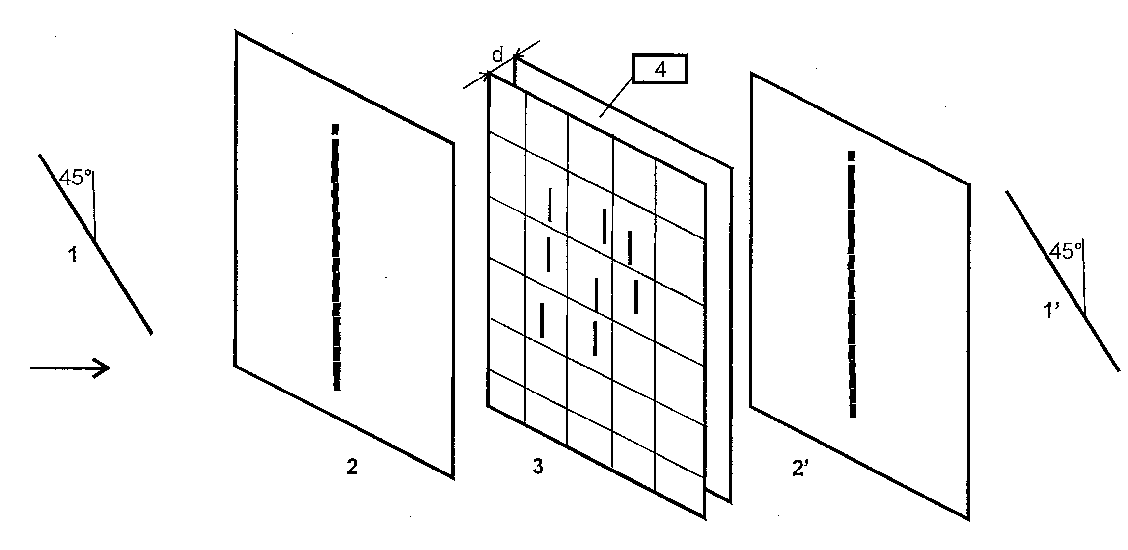
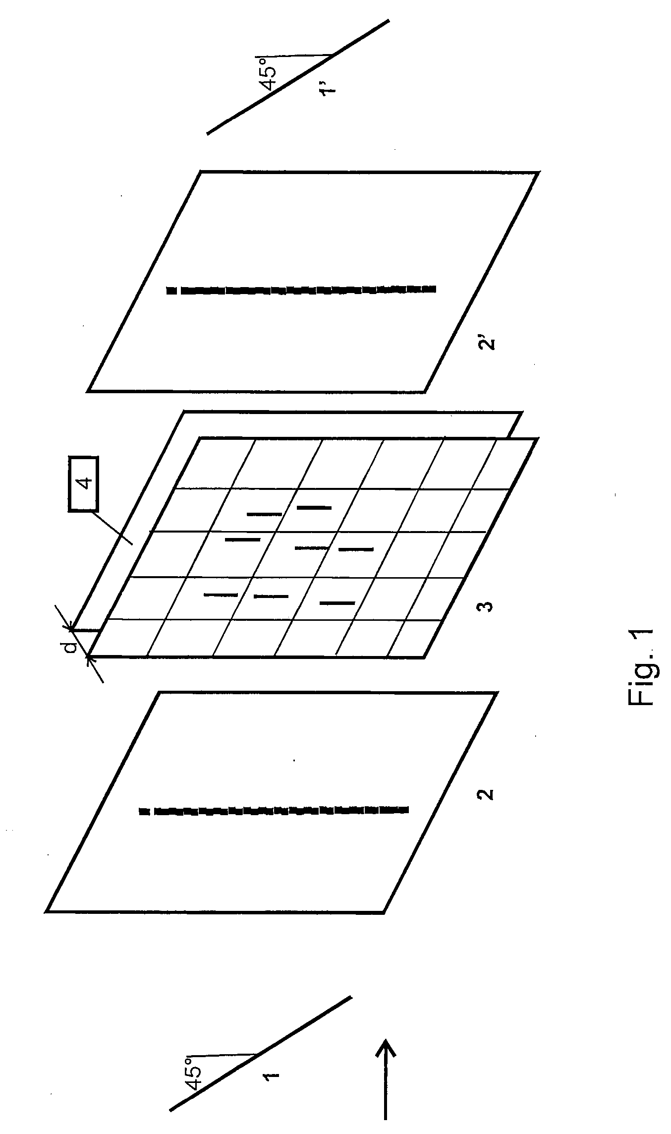
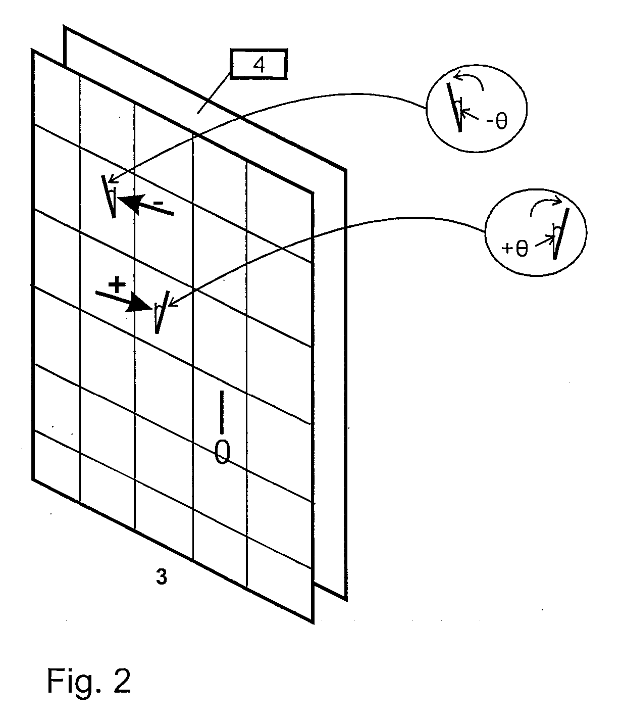
[0054]The inventive device for phase modulation of coherent light comprises a spatial light modulator (SLM), at least one light source means for illuminating the modulator matrix of the SLM, and a control unit for controlling the phase modulation of modulator cells of the modulator matrix. The modulator cells are LC modulator cells which are arranged regularly in rows and columns and which are preferably of rectangular shape. The function of the invention can also be realised with other forms of LC modulator cells. The control unit comprises memory units and computing units which communicate with each other with the help of software and hardware elements in order to generate and exchange data in order to control the LC modulator cells with control signals for a preferably three-dimensional image representation. The device for phase modulation can for example be integrated into a holographic display device.

[0055]The design of a controllable phase-modulating device is shown schematica...


PUM

PropertyMeasurementUnit
phase modulationaaaaaaaaaa
voltageaaaaaaaaaa
phase offsetaaaaaaaaaa

Abstract

A controllable device for phase modulation of coherent light with modulator cells comprising liquid crystal molecules is provided which realises a large number of phase steps per modulator cell and whose switching delay is shorter than 1 ms. The device can include a spatial light modulator with a modulator matrix having regularly arranged controllable LC modulator cells, a light source which illuminates the modulator matrix, and control means for controlling the phase modulation in the LC modulator cells. The modulator matrix can be configured to comprise a controllable λ/2 plate disposed between two non-controllable λ/4 plates; the controllable LC modulator cells can be PSS liquid crystal; each LC modulator cell is controllable locally with a positive or negative voltage value, depending on the actual phase values to be written; and the control means generate a globally constant phase offset for the phase values to be written in every other frame.

Description

CROSS-REFERENCE TO RELATED APPLICATIONS[0001]This application is based on and claims priority to German Application No. DE 10 2008 001 827.9, filed May 16, 2008, the entire contents of which are hereby incorporated by reference.BACKGROUND OF THE INVENTION[0002]The present invention relates to a device for phase modulation of coherent light with a spatial light modulator which comprises a modulator matrix with a regular arrangement of controllable LC modulator cells, with at least one light source which illuminates the modulator matrix, and with a control unit which controls the phase modulation in the LC modulator cells. A three-dimensional representation of images can be realised with this device if it is used as a display device.[0003]The field of application of this invention includes coherent-optical applications which comprise for modulating coherent light a liquid crystal (LC) device which is used to control the phase of the light in phase steps, whose number typically ranges ...

Claims


Application Information

Patent Timeline
Patent Type & Authority Applications(United States)
IPC IPC(8): G02F1/1335
CPCG02F1/13781G02F2001/133638G02F2203/04G02F2203/12G02F2203/50G02F2413/02G03H2240/42G03H1/2294G03H2001/0224G03H2225/32G09G3/003G09G3/3611G03H1/02G02F1/133638
Inventor LEISTER, NORBERT
Owner SEEREAL TECHNOLOGIES
Why Eureka
Try Eureka