Thermometer heater and thermistor

a heater and thermistor technology, applied in the field of electromechanical thermometers, can solve the problems of epoxie deformation, failure of epoxy and solder bonds, and difficulty in mounting the heater and the heat sensing element within the tip, so as to improve the heat transfer characteristics of the temperature sensing probe, reduce the number of probe failures, and reduce the time

Active Publication Date: 2009-11-19
WELCH ALLYN INC
View PDF18 Cites 12 Cited by
  • Summary
  • Abstract
  • Description
  • Claims
  • Application Information

AI Technical Summary

Benefits of technology

[0005]It is a further object of the present invention to reduce the number of probe failures in electronic thermometers.
[0006]A still further object of this invention is to eliminate the need of an over heat thermistor in the tip heating circuit of an electronic thermometer.
[0007]Another object of the present invention is to reduce the time needed to heat up the probe sensing tip of an electronic thermometer.
[0008]Yet another object of the present invention is to improve the heat transfer characteristics of a temperature sensing probe.
[0009]While a still further object is to reduce the cost of manufacturing a heat sensing probe of the type employed in electronic thermometers.
[0010]These and further objects of the present invention are attained by means of a temperature sensing probe having an elongated hollow shaft that is attached at its proximal end to a base housing and has a temperature sensing tip at its distal end. The tip contains an outer shell and an inner shell mounted therein to provide a space between the two shells. A heater is mounted on the outer surface of the inner shell along with a temperature sensing element. Electrical lead that pass through the shaft are connected to the heater and the heat sensing element by pairs of thick film conductive traces that are painted upon the outer surface of the inner shell. A heating element in the form of a thick film resistive member is connected between one pair of traces while the heat sensor is connected between the second pair of traces. Appropriate electric lead couple the traces to a power source and a processor found within the base housing. A thermally conductive epoxy fills the space between the two shells to provide for rapid heat transfer through the space.

Problems solved by technology

Because of the limited space available inside the probe tip, mounting the heater and the heat sensing element within the tip has proven to be difficult.
Some epoxies degrade with use, and the heater elements tend to overheat causing both epoxy and solder bonds to fail.
In addition some epoxies are not good thermal conductors and thus can disrupt the heat flow through the tip producing erroneous temperature readings.
A thermistor is generally provided in the heater circuitry to insure that the heater does not overheat, however, the use of the thermistor increases the overall cost of the system.

Method used


Image

  • Thermometer heater and thermistor
  • Thermometer heater and thermistor
  • Thermometer heater and thermistor

Examples


Embodiment Construction

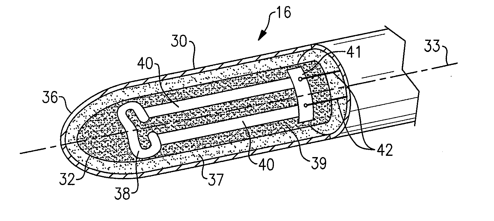
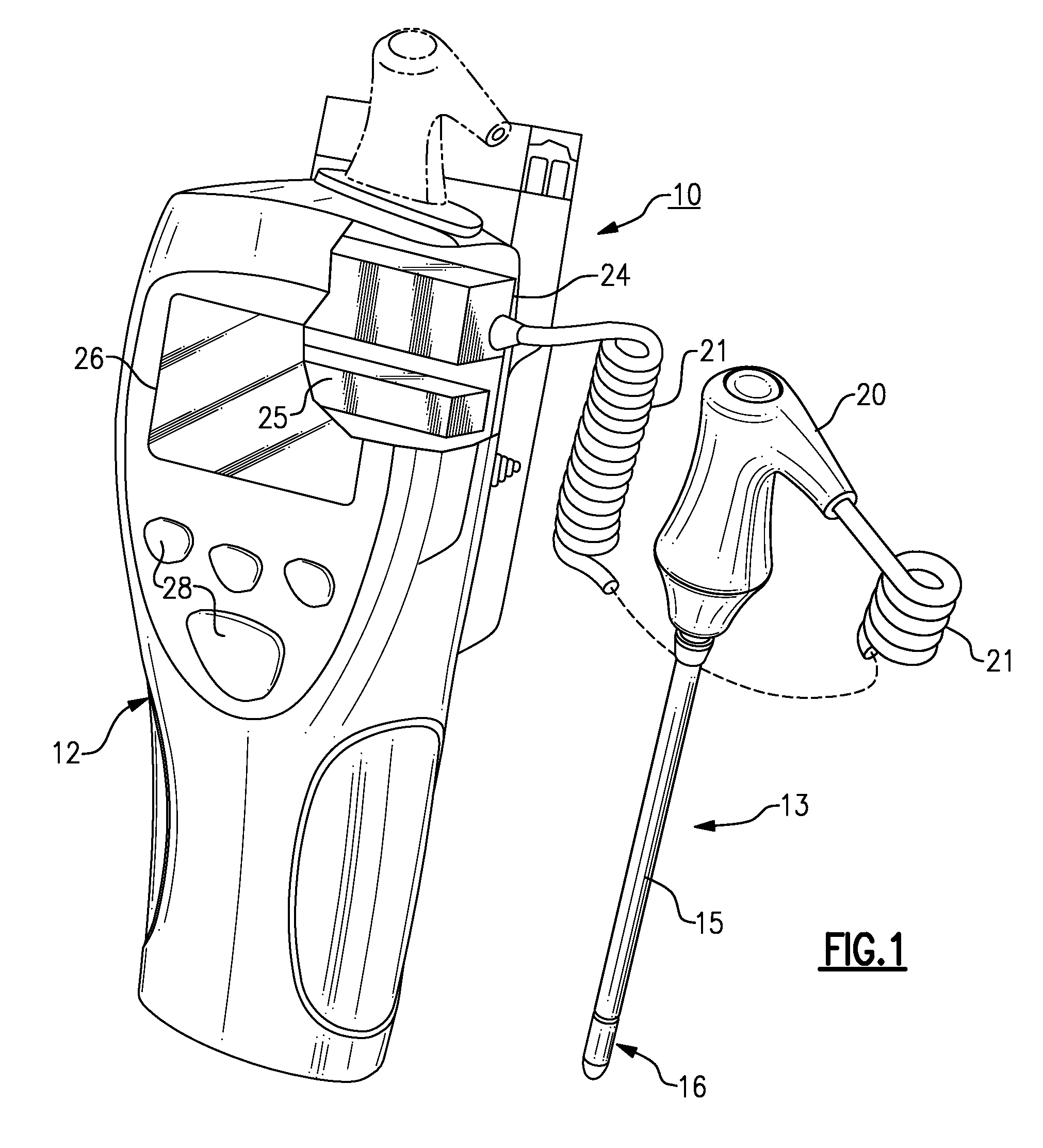
[0017]Turning initially to FIG. 1, there is illustrated an electronic thermometer, generally referenced 10, for measuring a patient's body temperature. The thermometer is portable and is intended for use in medical applications. The thermometer includes a compact base housing 12 and a temperature sensing probe 13. The sensing probe includes an elongated hollow shaft 15 having a sensing tip 16 affixed to its distal end. As will be described in further detail below, the tip contains a heating element and a heat sensor. A handle 20 is attached to the proximal end of the probe which, in turn is coupled to the base housing by a flexible cord 21. A micro processor 24 is stored in the housing along with a power supply 25 containing a rechargeable battery (not shown). A screen 26 is located on the face of the base housing for displaying the patient's body temperature along with a series of switches 28-28 by which the user can control the activity of the instrument. The processor contains so...


PUM

PropertyMeasurementUnit
response timeaaaaaaaaaa
temperatureaaaaaaaaaa

Abstract

A thermometric apparatus for determining a patient's temperature having a elongated sensing probe that is connected to a base housing. The insertion tip of the probe contains a outer shell and a spaced apart inner shell. The outer surface of the inner shell has a heater that is fabricated of a resistive thick film material and a heat sensor mounted thereon. The heater and the heat sensor are connected to a pair of thick film conductive traces which in turn are electrically attached by a flexible circuit board to leads running back to the base housing. The space between the two shells is filled by a thermally conductive epoxy.

Description

FIELD OF THE INVENTION[0001]This invention relates generally to an electronic thermometer and, in particular, to an electronic thermometer having an improved heat sensing probe tip.BACKGROUND OF THE INVENTION[0002]Electronic thermometers for measuring a patient's body temperature via a slim temperature probe have been in use for quite some time and have proven their worth in health care facilities as well as in the hands of patients themselves. Typically this type of thermometer includes a portable base housing having a processor for processing data provided by sensing elements generally located at the tip end of a rather small diameter probe. The patient temperature is determined from the data and displayed visually upon a viewing screen such as an LCD. Electronic thermometers of this type are disclosed in detail in U.S. Pat. Nos. 5,632,555; 6,000,846; 6,036,361; 6,827,488 and 6,971,790, the disclosures of which are incorporated herein by reference and are commercially available th...

Claims


Application Information

Patent Timeline
Patent Type & Authority Applications(United States)
IPC IPC(8): G01K7/00
CPCG01K13/002G01K1/16G01K13/20
Inventor STONE, RAY D.NEWMAN, RICHARD W.
Owner WELCH ALLYN INC
Why Eureka
Try Eureka