
Blade for a Wind Turbine Rotor

Inactive Publication Date: 2009-11-19
LM GLASSFIBER
View PDF8 Cites 17 Cited by
  • Summary
  • Abstract
  • Description
  • Claims
  • Application Information

AI Technical Summary

Benefits of technology

[0008]According to the invention, this object is achieved by a surface zone with a plurality of indentations and / or projections being provided in at least the root area, said indentations and / or projections being formed and dimensioned to improve the wind flow across the surface of the blade, i.e. reducing the separation behind the trailing edge of the blade (or root area) during rotation of the rotor. The principles known from the golf ball with respect to creating a turbulent air flow are thus utilised. In this way, the aerodynamic air resistance of the root part is reduced, thus allowing for an increase in wind turbine production and a reduction of storm loads on the blade. This is particularly applicable for especially large blades and blades with hub extenders. Preferably, the surface zone comprises a large number of indentations and / or projections.
[0010]According to a preferred embodiment of the blade according to the invention, the surface zone extends substantially along the entire length of the root area. Thus, the air resistance is reduced along the entire length of the root area.
[0021]The surface zone may also comprise a plurality of hexagonal indentations, which allows a further reduction of air resistance. Of course, the surface zone may also comprise a combination of indentations or projections having various shapes, such as any polygonal shape.
[0026]Alternatively, the indentations and / or projections may be a part of a covering, such as a tape or a film, provided on the surface of the blade. This allows the manufacture of blades by means of existing moulds, and the surface of the blade is supplied with said covering first after the blade has been moulded.

Problems solved by technology

This again results in problems when having to mount the blade to the hub, and, moreover, this causes great loads when the blade is mounted, such as storm loads, due to the large surface area of the blade.
Due to the circular cross-section, the root area does not contribute to the production of the wind turbine and, in fact, lowers the production a little because of wind resistance.
The larger the separation behind the golf ball, the larger the pressure loss behind the golf ball.
Therefore, golf balls have dimples, which causes the airflow around the golf ball to change from laminar to turbulent, which again makes the air flow “stick” to the surface of the golf ball for a longer period and reduces the separation behind the golf ball.

Method used


Image

  • Blade for a Wind Turbine Rotor
  • Blade for a Wind Turbine Rotor
  • Blade for a Wind Turbine Rotor

Examples


Embodiment Construction

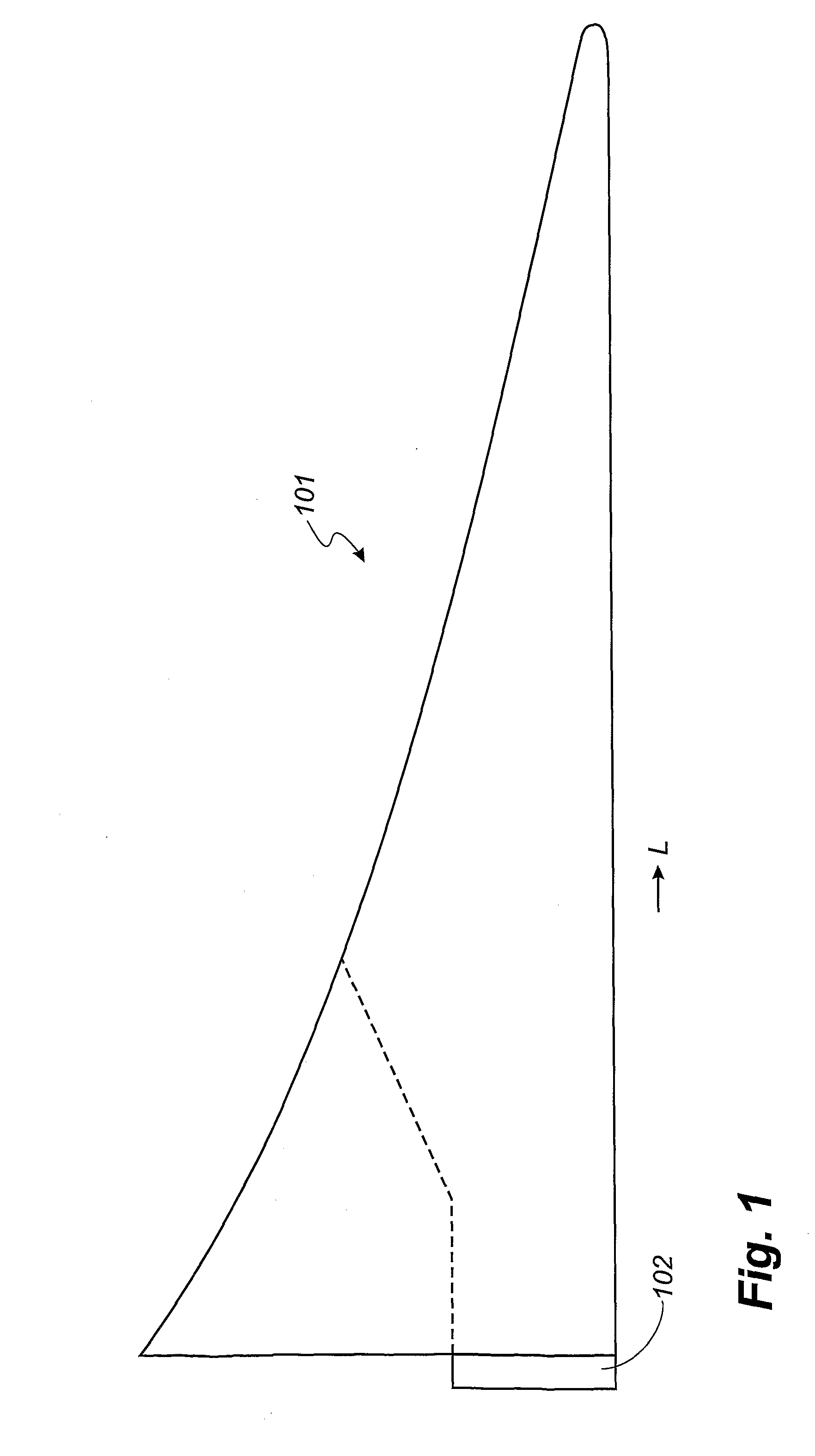
[0035]FIG. 1 shows an embodiment of an ideal blade 101 of the airfoil type. The blade is provided with a root part 102 adapted to be secured to a hub of a wind turbine. The ideal blade 101 is designed such that the width of the blade 101 decreases with increasing distance L from the hub. Furthermore, the first derivative of the width of the depicted blade 101 also decreases with increasing distance from the hub 101, which means that, ideally, the blade 101 is very wide at the root area 102. This causes problems with respect to securing the blade 101 to the hub. Moreover, when mounted, the blade 101 impacts the hub with large storm loads because of the large surface area of the blade 101.

[0036]Therefore, over the years, the construction of blades has developed towards a shape, where the outer part of the blade corresponds to the ideal blade 101, whereas the surface area of the root area is substantially reduced compared to the ideal blade. This embodiment is illustrated with a dashed...


PUM

PropertyMeasurementUnit
Lengthaaaaaaaaaa
Lengthaaaaaaaaaa
Lengthaaaaaaaaaa

Abstract

A blade (1) for a wind turbine rotor having a substantially horizontal rotor shaft, said rotor comprising a hub, comprises, seen in longitudinal direction along a longitudinal axis (10), a root area (2) closest to the hub, an airfoil area (4) furthest away from the hub and a transition area (3) between the root area (2) and the airfoil area (4). Seen in transverse direction, the blade (1) comprises a leading edge (5) and a trailing edge (6) as well as a chord plane (K) extending between the leading edge (5) and the trailing edge (6) of the blade (1). A surface zone with a plurality of indentations (7) and / or projections is provided in at least the root area (2), said indentations and / or projections being formed and dimensioned to improve the wind flow across the surface of the blade (1).

Description

TECHNICAL FIELD[0001]The present invention relates to a blade for a wind turbine rotor having a substantially horizontal rotor shaft, said rotor comprising a hub, where, seen in longitudinal direction along a longitudinal axis, the blade comprises a root area closest to the hub, an airfoil area furthest away from the hub and optionally a transition area between the root area and the airfoil area, and where, seen in transverse direction, said blade comprises a leading edge and a trailing edge as well as a chord plane extending between the leading edge and the trailing edge of the blade, wherein the root area has a substantially circular cross-section.BACKGROUND ART[0002]Ideally, a blade of the airfoil type is shaped like a typical aeroplane wing, where the chord plane width of the blade as well as the first derivative thereof increase continuously with decreasing distance to the hub. This results in the blade, ideally, being comparatively wide in the vicinity of the hub. This again r...

Claims


Application Information

Patent Timeline
IPC IPC(8): F03D11/00
CPCF03D1/0633F05B2240/32F05B2250/131F05B2250/132F05B2250/141Y02E10/721F05B2250/28F05B2250/70F05B2250/712F05B2280/6011F05C2253/12F05B2250/18Y02E10/72
Inventor GRABAU, PETER
Owner LM GLASSFIBER
Features
  • Generate Ideas
  • Intellectual Property
  • Life Sciences
  • Materials
  • Tech Scout
  • Unparalleled Data Quality
  • Higher Quality Content
  • 60% Fewer Hallucinations
Learn More