
Fuel cell system and control method thereof

Inactive Publication Date: 2009-11-19
HONDA MOTOR CO LTD
View PDF3 Cites 14 Cited by
  • Summary
  • Abstract
  • Description
  • Claims
  • Application Information

AI Technical Summary

Benefits of technology

[0011]An object of the present invention is to provide a fuel cell system and a control method thereof which performs a scavenging process during shutdown of the fuel cell, whereby it is possible to ensure stable electricity generation after startup and to startup more quickly.
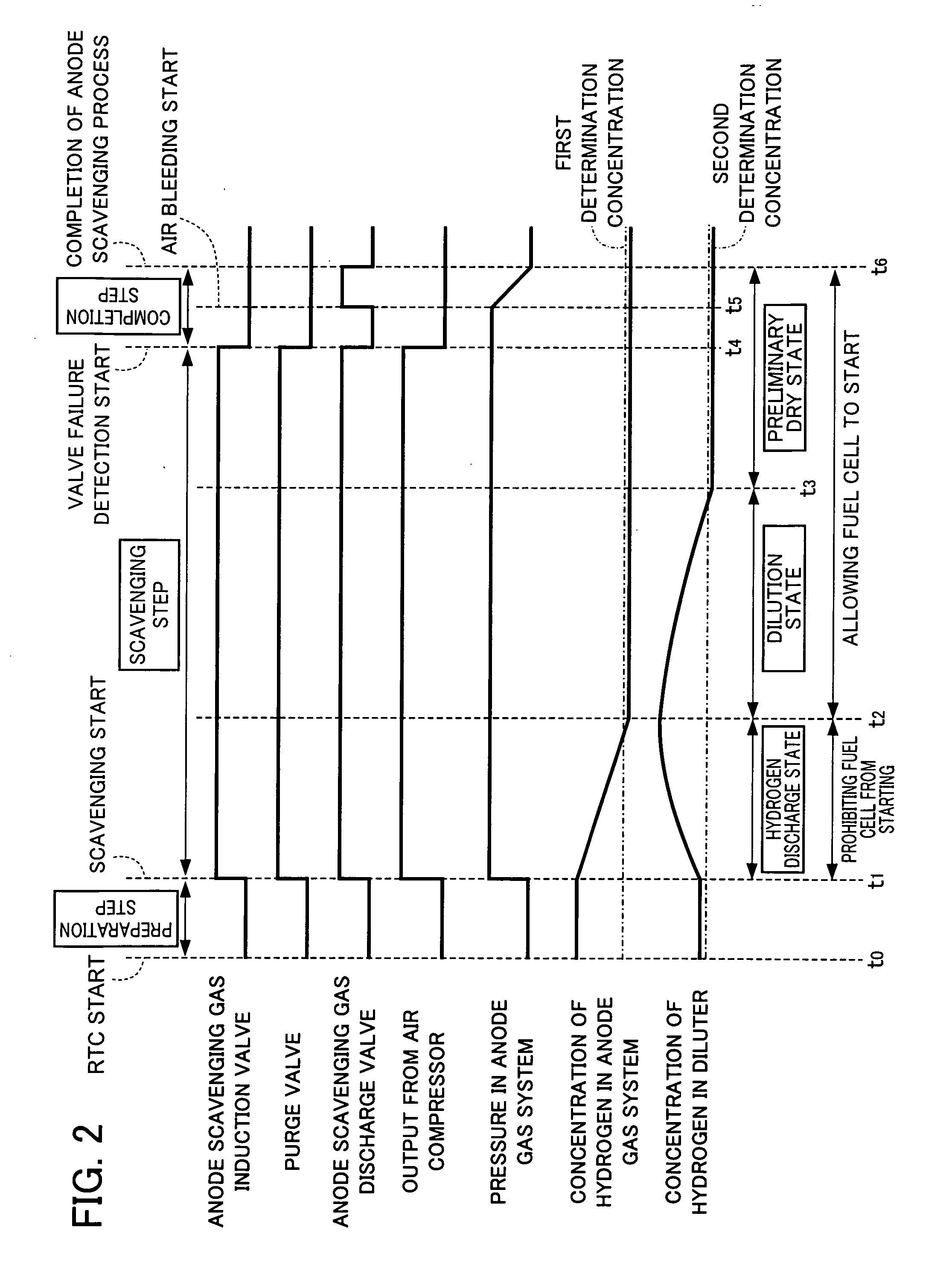
[0013]According to the present invention, whether to continue the scavenging process and prohibit the fuel cell from starting, or to suspend the scavenging process and allow the fuel cell to start, is determined based on the first gas concentration detected by the first gas concentration detection means, when a startup request for the fuel cell is detected while the scavenging process of the anode gas system is being performed. In this way, when a startup request is detected while the scavenging process is being performed, the fuel cell may be able to start quickly without waiting until this scavenging process has completed. Here in particular, whether to allow the fuel cell to start or to prohibit the fuel cell from starting is determined in response to the concentration of anode gas in the anode gas system.
[0014]Therefore, marketability of the fuel cell system can be improved by ensuring stable electricity generation after startup of the fuel cell, as well as startup more quickly.
[0016]According to the present invention, the first gas concentration is detected when a startup request for the fuel cell is detected while the scavenging process of the anode gas system is being performed and, in a case where the detected first gas concentration is greater than the first determination concentration, the scavenging process is continued and startup of the fuel cell is prohibited. In this way, the fuel cell is prevented from being allowed to start when the scavenging process is not substantially completed, whereby marketability of the fuel cell system.
[0019]According to the present invention, in a case where the purge process that replaces gas in the anode gas system with newly supplied anode gas is performed after the startup of the fuel cell is allowed, the replacing amount of gas during this purge process decreases as a second gas concentration detected by the second gas concentration detection means increases. In this way, the purge process is performed in accordance with the concentration of anode off gas remaining in the dilution means, whereby the time for this purge process can be shortened. Therefore, the fuel cell can start quickly, which can improve the marketability of the fuel cell system.
[0021]According to the present invention, when the purge process is performed after the fuel cell is allowed to start, the second gas concentration is detected and, in a case where this second gas concentration is not greater than a predetermined second determination concentration, the replacing amount of gas during this purge process is maintained. Thus, the time for this purge process can be shortened. Therefore, the fuel cell can start more quickly, whereby marketability of the fuel cell system is improved.

Problems solved by technology

When the fuel cell system is left in an environment in which the outside temperature is below freezing after electric power generation has stopped, the residual water freezes in the fuel cell and the reactive gas flow channel, and it becomes difficult to ensure the stability of electricity generation from the fuel cell when the fuel cell system is started the next time.
In such a fuel cell system, stable electricity generation after startup can be ensured; however, when a driver turns on the ignition in order to instruct startup of the fuel cell while the scavenging process is being performed, it is necessary to wait for the scavenging process to be completed to actually startup, whereby marketability may suffer.

Method used


Image

  • Fuel cell system and control method thereof
  • Fuel cell system and control method thereof
  • Fuel cell system and control method thereof

Examples


Embodiment Construction

[0034]One embodiment of the present invention is described hereinafter with reference to the accompanying drawings.

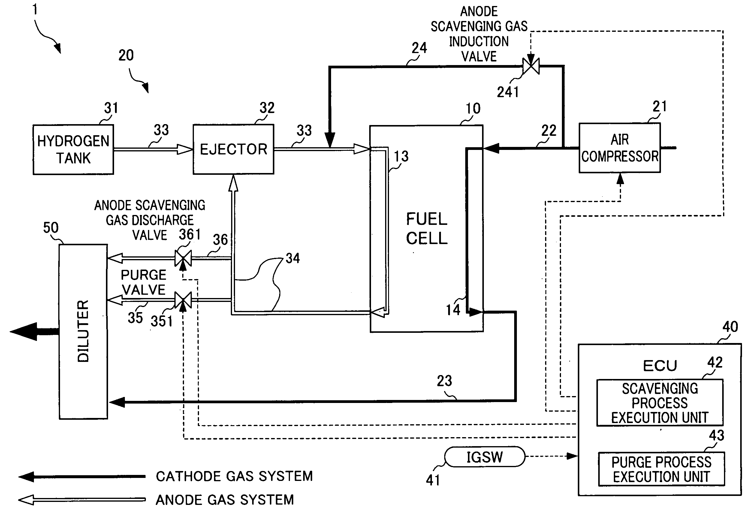
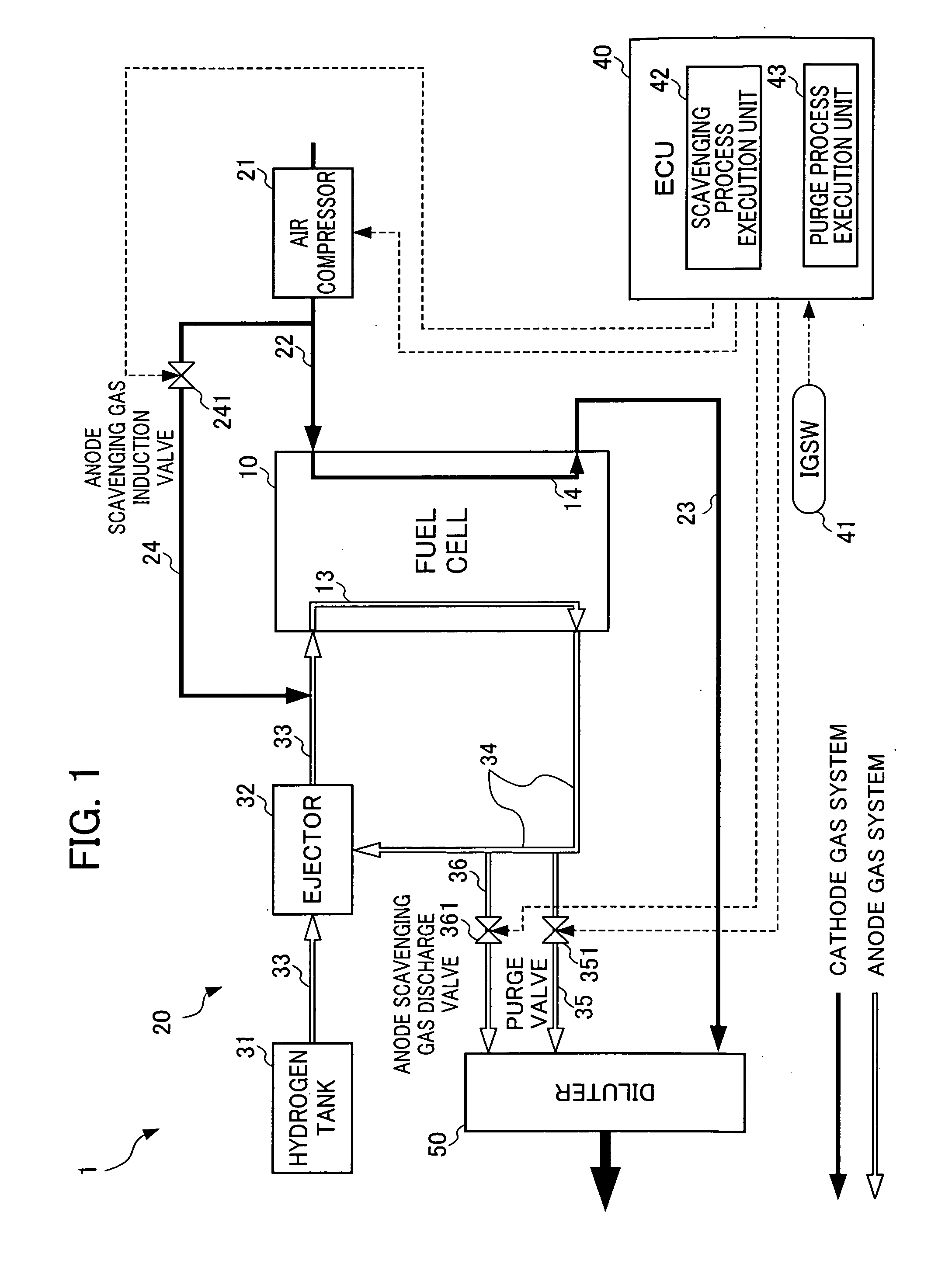
[0035]FIG. 1 is a schematic diagram of the fuel cell system 1 according to the present embodiment.

[0036]The fuel cell system 1 has a fuel cell 10, a supply device 20 supplying anode gas and cathode gas to this fuel cell 10, and an electronic control unit (hereinafter referred to as “ECU”) 40 that controls the fuel cell 10 and the supply device 20. This fuel cell system 1 is mounted on a fuel cell vehicle (not shown) that has electric power generated by the fuel cell 10 as a source of driving power.

[0037]The fuel cell 10 can be configured with a plurality, for example, tens or hundreds, of stacked cells. Each of the cells has a membrane electrode assembly (MEA) placed between a pair of separators. The MEA is configured with two electrodes which are an anode (negative electrode) and a cathode (positive electrode), and a solid polymer electrolyte membrane placed between th...


PUM


Abstract

The present invention provides a fuel cell system and a control method thereof that performs a scavenging process when the fuel cell is stopped, whereby stable electrical power production is ensured after startup, and faster startup is possible. The fuel cell system performs the scavenging process in which scavenging gas is supplied into an anode gas system when the fuel cell is stopped. When a startup request for the fuel cell is detected while the anode scavenging process is being performed, the concentration of hydrogen in the anode gas is detected, and then whether to continue the anode scavenging process and prohibit the fuel cell from starting, or to suspend the anode scavenging process and allow the fuel cell to start is determined based on this detected concentration of hydrogen in the anode gas system.

Description

[0001]This application is based on and claims the benefit of priority from Japanese Patent Application No. 2008-130666, filed on 19 May 2008, the content of which is incorporated herein by reference.BACKGROUND OF THE INVENTION[0002]1. Field of the Invention[0003]This invention relates to a fuel cell system. More particularly, the present invention relates to a fuel cell system performing a scavenging process for an anode gas system when the fuel cell is stopped.[0004]2. Related Art[0005]In recent years, fuel cell systems have gained the spotlight as a new power source for automotive vehicles. A fuel cell system is provided with, for example, a fuel cell that generates electric power by chemically reacting reactive gases and a reactive gas supply device that supplies the fuel cell with the reactive gases via a reactive gas flow channel.[0006]For example, the fuel cell consists of a plurality, for example, tens or hundreds, of stacked cells. In such an example, each cell is configured...

Claims


Application Information

Patent Timeline
IPC IPC(8): H01M8/04
CPCH01M8/04097H01M8/04179Y02E60/50H01M8/04231H01M2008/1095H01M8/04223H01M8/04302H01M8/04225
Inventor MATSUMOTO, YUJIUEHARA, JUNJIUEDA, KENICHIRO
Owner HONDA MOTOR CO LTD
Learn More