
Scheduling methods and systems for multi-hop relay in wireless communications

Active Publication Date: 2009-11-19
ACER INC
View PDF1 Cites 26 Cited by
  • Summary
  • Abstract
  • Description
  • Claims
  • Application Information

AI Technical Summary

Benefits of technology

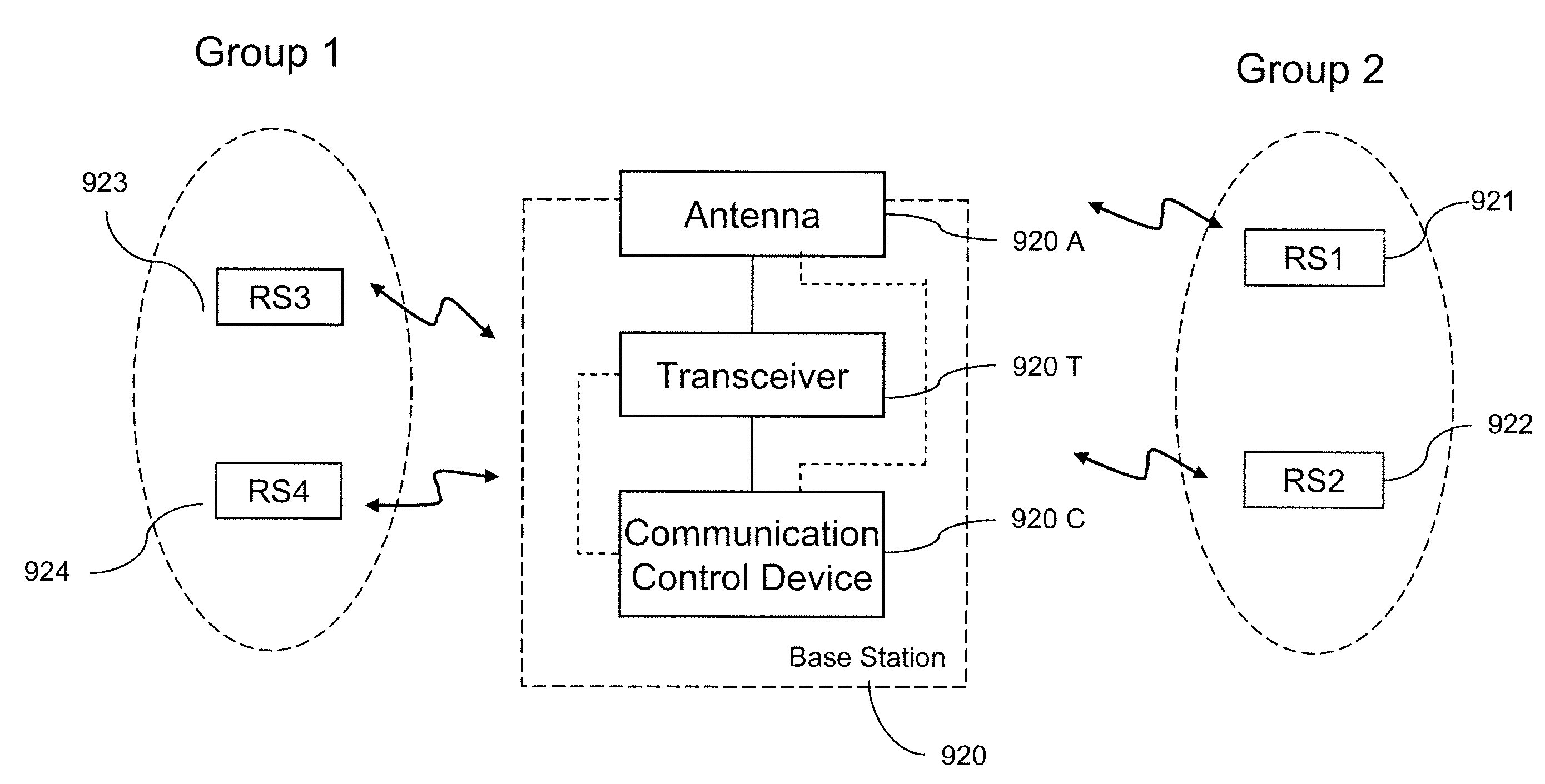
[0018]Accordingly, the present invention is directed to a transmission scheduling method for a wireless multi-hop relay communication system, wherein relay stations are disposed within the coverage area of a base station for serving users with poor link quality to the base station. In the present invention, base stations and relay stations are equipped with directional antennas or sector antennas to further exploit the advantage of spatial separations inherited in the environment, and through the mechanism of grouping and permutation of transmission scheduling, interference inside a single cell and between adjacent cells is reduced, accordingly, the capacity of the system is improved.
[0020]The transmission scheduling mechanism in the present invention is described as follows with time division duplex access as example. When a base station serves the relay stations of a particular group with directional antennas or sector antennas, the relay stations of other groups which are not served by the base station during this period serve users within their coverage areas by appropriate power control. According to the transmission scheduling mechanism, users of different groups can have time division multiple accesses with divisions in the time domain, while the relay stations within the same group can reuse the radio resources at the same time and on the same frequency through the characteristic of spatial separation, so that the transmission efficiency and the capacity of the system can be improved.
[0021]In a multi-cell structure, transmission scheduling between adjacent cells can be achieved by permuting group service order of the transmission scheduling of single cells. As to any two adjacent cells A and B, when the base station in cell A serves a particular group j in cell A during the ith phase, the base station in the adjacent cell B serves another group k in cell B which has less interference to group j in cell A during the ith phase, thus, high spectrum efficiency and high transmission efficiency of the system can be achieved.

Problems solved by technology

Users located at cell boundary have worse link quality due to the long transmission distance to the base station, and users in the cell with severe shadowing effect also have worse link quality, thereby the foregoing users cannot perform high-speed data transmissions.
However, the cost of the base stations and the cost of the backhaul network connections will be substantially increased by the aforementioned method.
However, if the transmission power is increased, not only the transmission cost will be increased but also the interference level will be increased.
However, since the same data will be duplicated and relayed over the air multiple times for multi-hop transmissions, it consumes the radio resources.
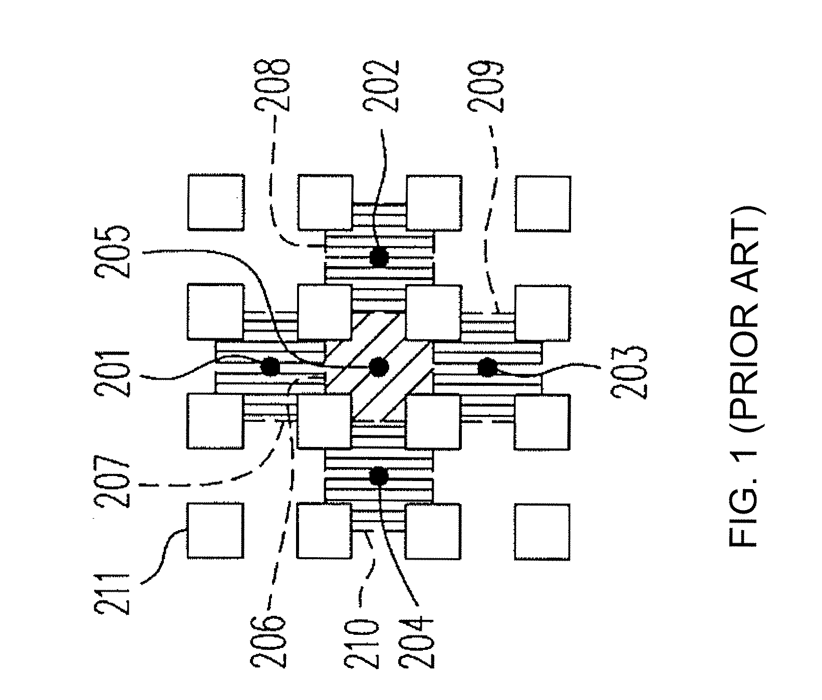
However, since the relay stations are disposed outside of the coverage area 206 of the base station, each relay station requires an additional directional antenna pointing at the base station for communicating with the base station, and which increases the hardware cost of the relay stations.
The main purpose of the relay stations is to extend the coverage area of the base station, however, the link quality of users at the boundary of the service range of the base station cannot be improved.
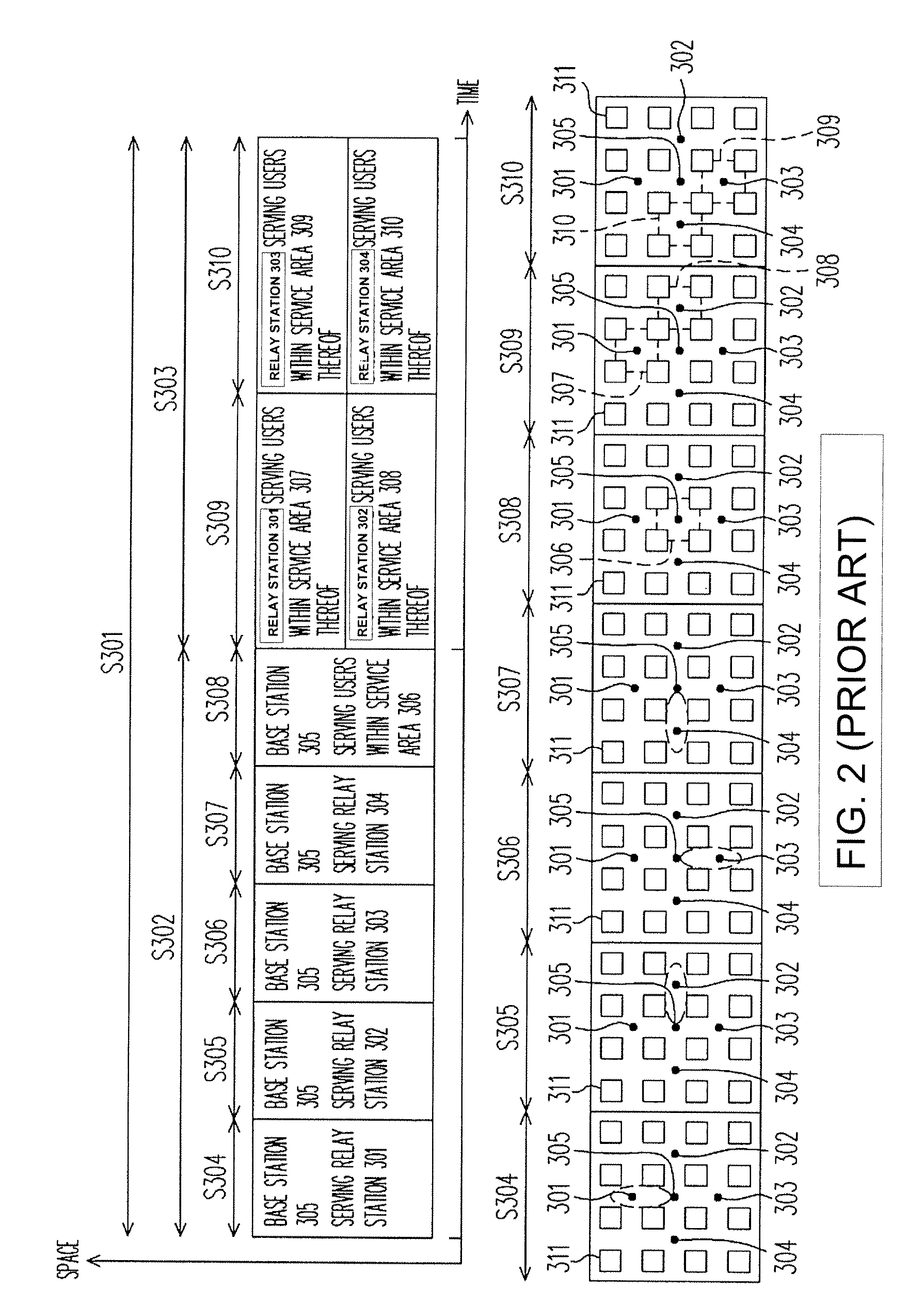
Besides, all the base station are idled for some time durations in the frame structure, since base stations are the only serving stations connected to the backhaul networks and carrying the effective data, the transmission efficiency of the base station in this design is not ideal.
When considering the multi-cell structure, because of the use of omni-directional antennas, the reuse factor of at least 2 is required to avoid the severe inter-cell interference, and thus decreases the overall system capacity.
Regardless of the first layout or the second layout that all serving stations are equipped with omni-directional antennas, all the base station and the relay stations are idled for some time in the frame structure, thus, the transmission efficiency thereof is not ideal.

Method used


Image

  • Scheduling methods and systems for multi-hop relay in wireless communications
  • Scheduling methods and systems for multi-hop relay in wireless communications
  • Scheduling methods and systems for multi-hop relay in wireless communications

Examples


Embodiment Construction

[0037]The following embodiments will be described with a Manhattan-like environment as an example, and those having ordinary knowledge in the art should be able to implement the present invention in any other environment according to the spirit of the present invention and the descriptions of the following embodiments. In following embodiments, interference level is weakened by spatial separation produced by the shadowing effect of surrounding buildings in a Manhattan-like environment.

[0038]FIG. 8 illustrates the layout of relay stations in a Manhattan-like environment according to an embodiment of the present invention. Referring to FIG. 8, a microcell covers 690*690 square meters, and the base station 805 is disposed at a crossroad and four relay stations 801, 802, 803, and 804 are disposed at intersections of the two crossed streets with other streets in four directions, which is, the relay stations 801˜804 are disposed at the intersections of the line of sight (LOS) and the non ...


PUM


Abstract

A scheduling technique for wireless multihop relay communication systems is provided. With spatial separation caused by the shadowing effect of surrounding buildings, a base station and its relay stations in a single cell are divided into several groups by following the rule that stations with severe potential interference are separated into different groups. The base station arranges the scheduling of these groups and serves these groups sequentially in the time domain. To take advantage of shadow effect, the same radio resources can be scheduled for relay stations within the same group due to the isolation of interfering signals. In the present invention, base stations and relay stations are equipped with directional antennas or sector antennas to further exploit the advantage of spatial separations. Different relay groups can also reuse the radio resource through appropriate power control. The cell capacity can be enhanced substantially because of aggressive radio resource reuse.

Description

CROSS-REFERENCE TO RELATED APPLICATION[0001]This application claims the priority benefit of Taiwan application serial no. 95137676, filed Oct. 13, 2006. All disclosure of the Taiwan application is incorporated herein by reference.BACKGROUND OF THE INVENTION[0002]1. Field of the Invention[0003]The present invention relates to a method for grouping relay stations in a wireless multi-hop relay communication system and a system thereof. More particularly, the present invention relates to a scheduling method for a wireless multi-hop relay communication system for improving the transmission efficiency and capacity of the system.[0004]2. Description of Related Art[0005]Next generation mobile communication systems are envisioned to provide high-speed, high link quality, and high security transmissions, and are also expected to support various communication services. An effective resource schedule / allocation method has to be established to meet different quality of service (QoS) requirements...

Claims


Application Information

Patent Timeline
IPC IPC(8): H04B7/14H04H20/71H04L12/26
CPCH04B7/2606H04B7/15507
Inventor LIN, SHIANG-JIUNFU, I-KANGPAI, CHENG-KANGSHEEN, WERN-HO
Owner ACER INC
Learn More