Arrangement to transmit magnetic resonance signals

Active Publication Date: 2009-11-19
SIEMENS HEALTHCARE GMBH
View PDF5 Cites 62 Cited by
  • Summary
  • Abstract
  • Description
  • Claims
  • Application Information

AI Technical Summary

Benefits of technology

[0012]An object of the present invention is to provide an improved

Problems solved by technology

The technical problems described below result due to the use of connection lines.
This causes heat to be generated in proximity to the patient.
To avoid such heat generations, low-attenuation cables are presently used for transmission but these have a large cable diameter and are correspondingly unwieldy.
An unwieldy cable bundle is likewise formed by the number of acquisition channels; the cable bundle is subjected to increased mechanical loads due to the movement of the patient bed, even given the use of cable plugs on the bed.
The problem of the cited cable bundle is aggravated by the fact that at least a part

Method used


Image

  • Arrangement to transmit magnetic resonance signals
  • Arrangement to transmit magnetic resonance signals
  • Arrangement to transmit magnetic resonance signals

Examples


Example

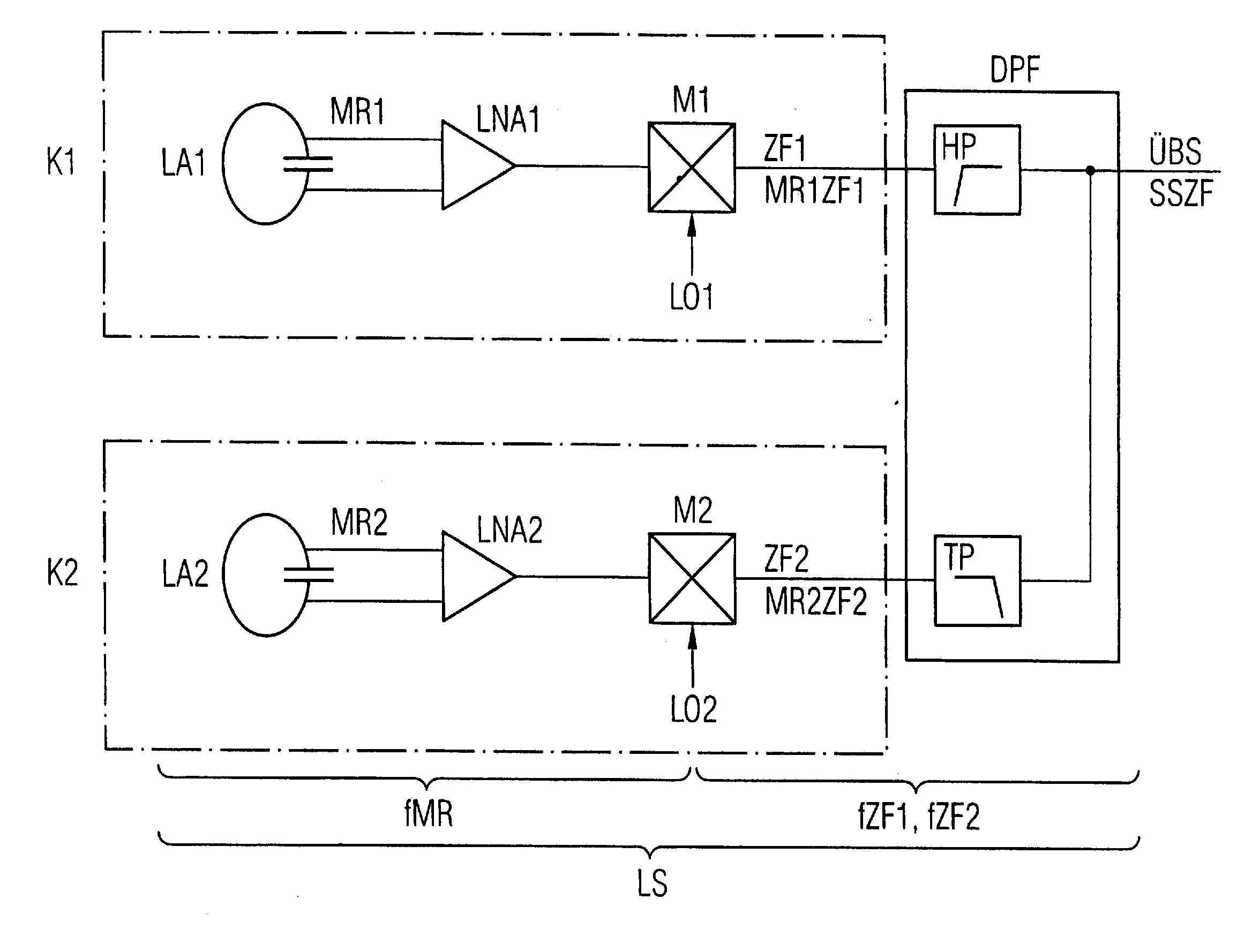
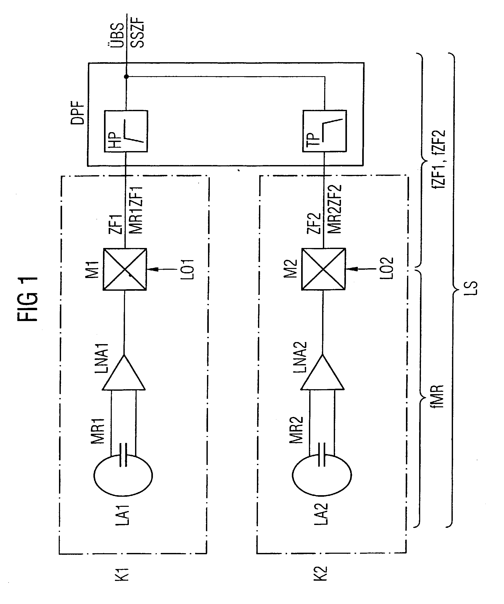
[0047]FIG. 1 shows the basic arrangement according to the invention for the transmission of two acquired magnetic resonance signals MR1 and MR2.

[0048]A local coil LS has, for example, a first branch or channel K1 and a second branch or channel K2.

[0049]The channels K1, K2 respectively contain a single antenna LA1 or LA2 a pre-amplifier LNA1 or LNA2 and a mixer M1 or M2.

[0050]A first single antenna LA1 designed as a loop antenna is associated with the first channel K1 while a second single antenna LA2 designed as a loop antenna is associated with the second channel K2.

[0051]A first magnetic resonance signal MR1 is acquired via the first single antenna LA1 while a second magnetic resonance signal MR2 is acquired via the first single antenna LA2.

[0052]The acquired first magnetic resonance signal MR1 arrives at a first mixer M1 via a first pre-amplifier LNA1 that is designed as a low noise amplifier.

[0053]A frequency conversion of the amplified first magnetic resonance signal MR1 into a...


PUM


Abstract

An arrangement for transmitting magnetic resonance signals, with a transmission link that connects a local coil with a receiver, has a first channel of the local coil with a first single antenna to acquire a first magnetic resonance signal, as well as a first mixer connected with the first single antenna. The first mixer forms an intermediate-frequency first signal from the supplied first magnetic resonance signal. A second channel of the local coil has a second single antenna to acquire a second magnetic resonance signal, as well as a second mixer connected with the second single antenna. The second mixer forms an intermediate-frequency second signal from the supplied second magnetic resonance signal. The local coil has a device for signal combination that, by frequency multiplexing, that combines the intermediate-frequency first signal of the first channel and the intermediate-frequency second signal of the second channel so that it arrives at the receiver via the transmission path. The receiver has an A/D converter at which one of the transmitted intermediate-frequency signals of an associated channel arrives in order to be sampled with a sampling frequency for digitization. For frequency conversion, a first local oscillator frequency is connected at the first mixer and a second local oscillator frequency is connected at the second mixer. the first and second local oscillator frequencies are selected such that intermediate-frequencies formed by the frequency conversion are mirror-symmetrical relative to the sampling frequency of the A/D converter.

Description

BACKGROUND OF THE INVENTION[0001]1. Field of the Invention[0002]The present invention concerns an arrangement to transmit magnetic resonance signals that are acquired by local coils.[0003]2. Description of the Prior Art[0004]Modern magnetic resonance systems simultaneously acquire a number of magnetic resonance signals via local antennas that are placed on the patient. These local antennas are components of what is known as a “local coil”. The acquired magnetic resonance signals are pre-amplified, conducted away from a central region of the magnetic resonance system and supplied to a shielded receiver in order to be used therein for image processing.[0005]The connection lines used for transmission are generally directed within a movable patient bed and are therefore several meters in length. The technical problems described below result due to the use of connection lines.[0006]The cables exhibit attenuations in the frequency range of the magnetic resonance signals to be transmitted;...

Claims


Application Information

Patent Timeline
IPC IPC(8): H04B7/00
CPCG01R33/3415G01R33/3607G01R33/3664G01R33/3635G01R33/3621
Inventor BIBER, STEPHANBOLLENBECK, JANOPPELT, RALPHVESTER, MARKUS
Owner SIEMENS HEALTHCARE GMBH
Why Eureka
Try Eureka