
Temperature compensated strain sensing catheter

a temperature-compensated, catheter technology, applied in the field of surgical catheters, can solve the problems of affecting the wavelength bandpass that is reflected by the grating, the fbg refractive index, and the use of strain sensors can be negatively impacted

Active Publication Date: 2009-11-19
ST JUDE MEDICAL INT HLDG SARL
View PDF100 Cites 79 Cited by
  • Summary
  • Abstract
  • Description
  • Claims
  • Application Information

AI Technical Summary

Benefits of technology

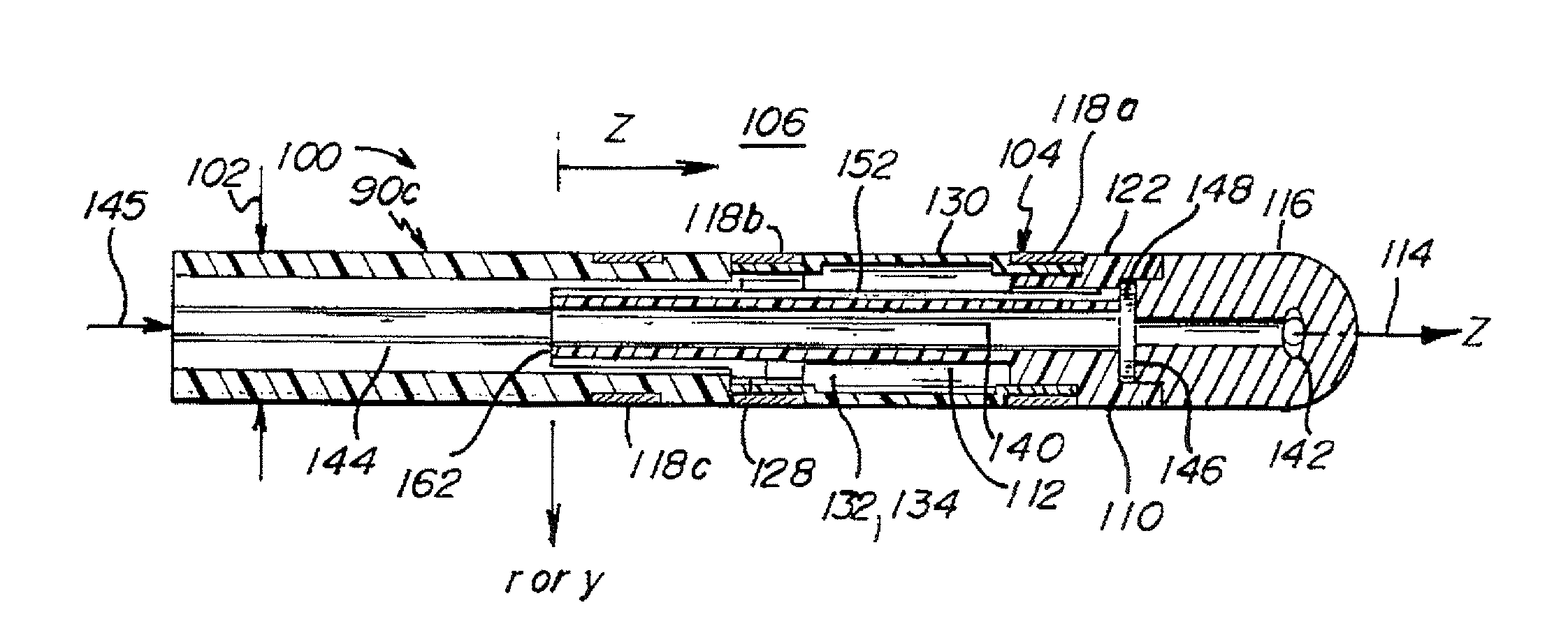
[0010]Thermal management techniques in accordance with various aspects of the invention may include reducing the axial conduction between a high temperature component of an end effector (e.g. an ablation head) and the optical fiber strain sensors. Thermal management technique in accordance with other aspects of the invention may include closer coupling of the optical fiber strain sensor to a controllable temperature sink, such as an irrigation flow stream. Still another thermal management technique in accordance with some embodiments of the invention may entail isolation of the optical fiber strain sensors from radial heating or cooling through the walls of the strain sensing assembly.
[0011]The temperature measurement techniques of the various embodiments may include measurement of a representative temperature of the optical fiber strain sensors. Such an approach may be adequate for applications or configurations where the thermal management of the optical fiber strain sensors produces a generally uniform temperature at a given axial location on the body of the strain sensing assembly. In other embodiments, the use of multiple temperature sensors may adequately characterize the thermal profile of the strain sensing assembly, providing representative temperatures of each optical fiber strain sensor.

Problems solved by technology

Temperature changes may also alter the refractive index of the FBG, further affecting wavelength bandpass that is reflected by the grating.
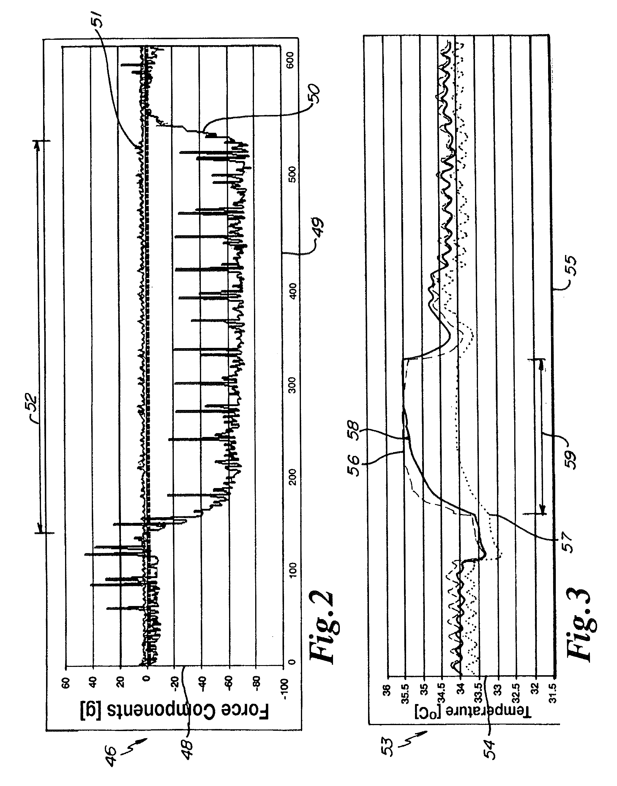
While optical fiber strain sensors can provide advantages for certain types of catheter procedures, the use of such strain sensors can be negatively impacted in situations involving temperature changes proximate the distal end of the catheter.

Method used


Image

  • Temperature compensated strain sensing catheter
  • Temperature compensated strain sensing catheter
  • Temperature compensated strain sensing catheter

Examples


Embodiment Construction

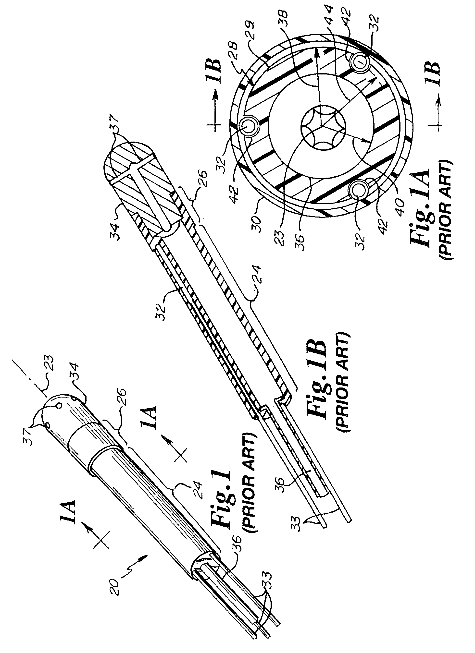
[0039]Referring to FIGS. 1, 1A and 1B, a strain sensing assembly 20 comprising a deformable body 22 that defines a central axis 23 having a sensing portion 24 and a collar portion 26 is depicted. The sensing portion 24 of the strain sensing assembly 20 is further characterized as including a stem 28 having an outer surface 29 that is shrouded by a sleeve 30. A trio of fiber Bragg gratings 32, each sourced via a fiber optic 33, are operatively coupled to the stem 28. In the depicted embodiment, the collar portion 26 is operatively-coupled to an ablation head 34. An irrigation passage 36 passes through the stem 28 and ablation head 34, terminating at the exterior of the ablation head 34 via a plurality of transpiration passages 37.

[0040]In this embodiment, the strain sensing assembly 20 is characterized as having a stem radius 38 that is approximately 3½ times the radius 40 of irrigation passage 36. The fiber Bragg gratings 32 are mounted in a trio of grooves 42 on the outer surface 2...


PUM


Abstract

A strain sensing assembly implements thermal management and / or temperature measurement techniques to adequately mitigate against and compensate for temperature changes in optical fiber strain sensors of a distal end of a catheter. In one embodiment, the distal end of the catheter includes an end effector such as an ablation head that introduces significant thermal temperature changes proximate the distal end of the catheter. In one embodiment, a plurality of temperature sensors is utilized for accurate determination of each of a plurality of optical fiber strain sensors. In other embodiments, a single temperature sensor may be utilized by implementing thermal management techniques that adequately reduce temperature differences between the single temperature sensor and the plurality of optical fiber strain sensors.

Description

FIELD OF THE INVENTION[0001]The present application is directed generally to surgical catheters with the ability to determine forces applied at a distal end of the catheter. More specifically, the present application is directed to a temperature compensated strain sensing catheter utilizing optical fiber strain sensors.BACKGROUND OF THE INVENTION[0002]Catheter systems utilizing light-based, optical fiber strain sensors to determine touching forces on a distal extremity of an end effector have found favor in recent years for the exploration and treatment of various organs or vessels with catheter-based diagnostic and treatment systems. Such light-based systems can be configured so that they are do not affect and are not affected by electromagnetic radiation environments.[0003]One such light-based catheter system is described in U.S. Pat. No. 6,470,205 to Bosselman which describes a robotic system for performing surgery comprising a series of rigid links coupled by articulated joints....

Claims


Application Information

Patent Timeline
IPC IPC(8): A61B6/00G02B6/00
CPCA61B5/00A61B5/6885A61B18/24A61B2562/0266A61B2017/00101A61B2019/464A61B19/46A61B90/06A61B2090/064
Inventor LEO, GIOVANNIAEBY, NICOLASVANENKOV, YURI
Owner ST JUDE MEDICAL INT HLDG SARL
Learn More