
Hybrid Photovoltaic Cell Module

a photovoltaic cell and hybrid technology, applied in the field of hybrid photovoltaic cell modules, can solve the problems of low efficiency of the second generation photovoltaic cells, low efficiency of the third generation photovoltaic cells, and high cost of production of photovoltaic cells, and achieve the effect of increasing light conversion efficiency

Inactive Publication Date: 2009-11-26
RAMESH SWAMINATHAN
View PDF20 Cites 5 Cited by
  • Summary
  • Abstract
  • Description
  • Claims
  • Application Information

AI Technical Summary

Benefits of technology

The present invention is about a new type of photovoltaic cell module that includes a substrate and a special photopolymer composition. This composition includes an organic photopolymer, nanoparticles, and a dendrimer. The dendrimer helps to disperse the nanoparticles in the photopolymer. This new type of photovoltaic cell module is more efficient and flexible than previous generations, and can be produced at a lower cost. The technical effect of this invention is to provide an improved hybrid photovoltaic cell that is both efficient and useful.

Problems solved by technology

However, these types of photovoltaic cells are expensive to produce due to an inherent cost of processing, handling silicon, and fabrication.
However, the second generation photovoltaic cells are not as efficient (˜9% efficiency) as the first generation photovoltaic cells.
However, the third generation photovoltaic cells typically exhibit poor efficiency of from 1-3%.
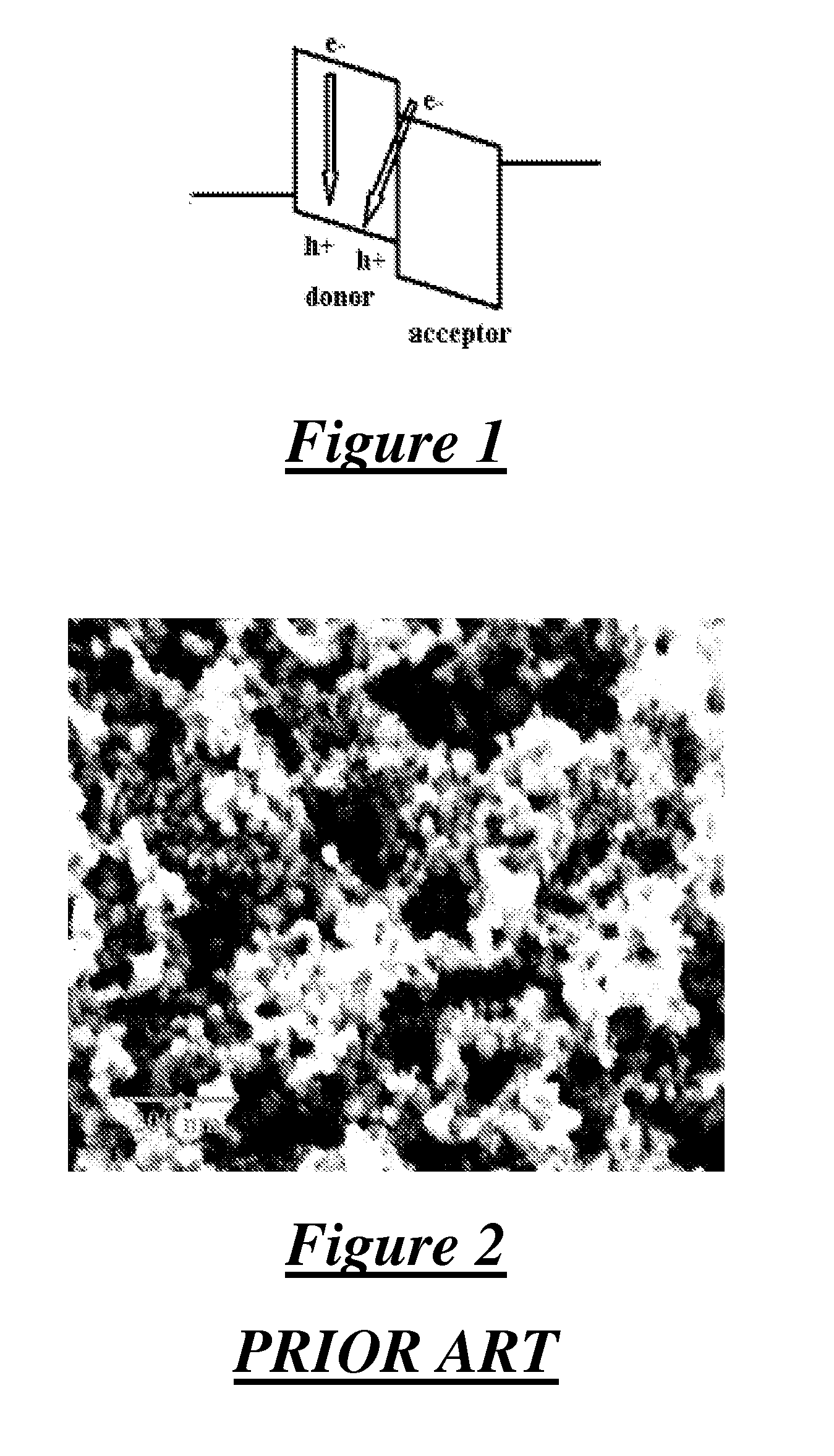
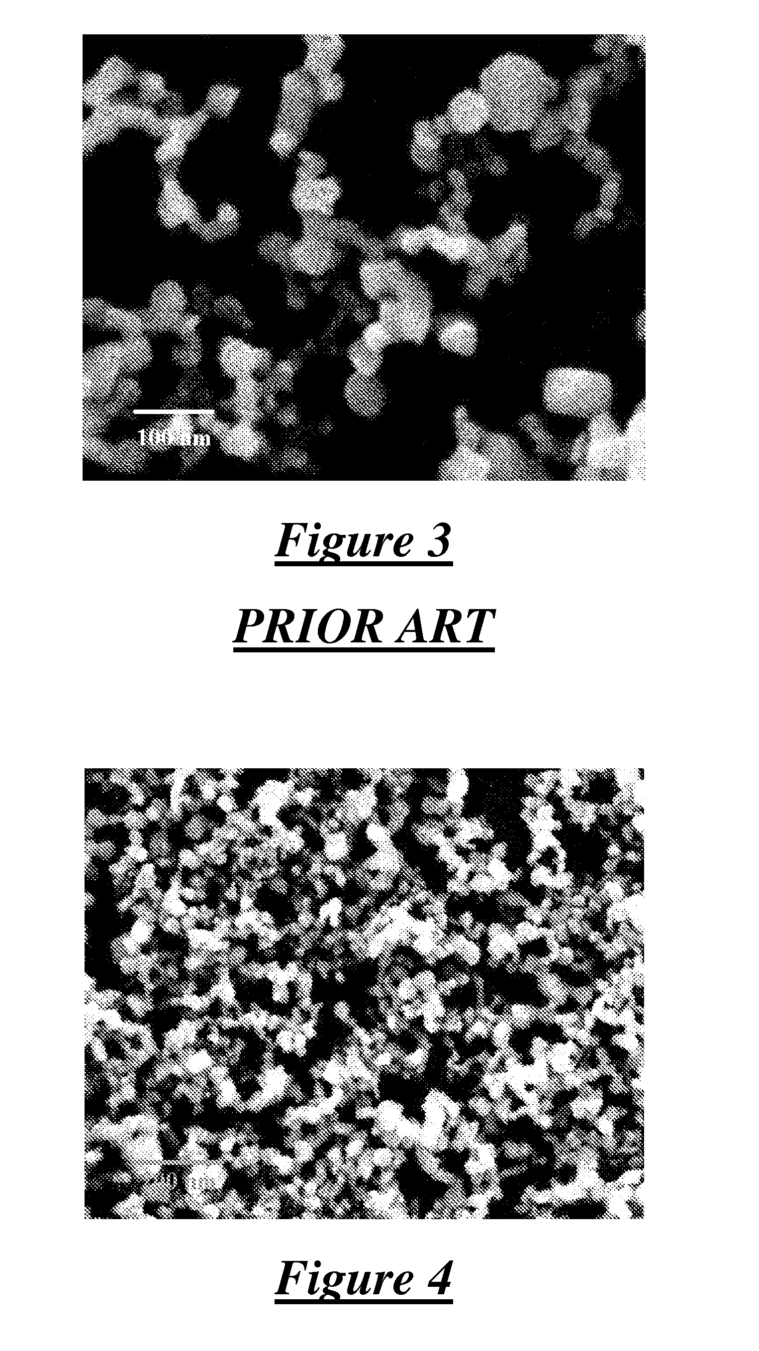
However, when used in these types of photovoltaic cells, the nanoparticles tend to agglomerate and are not maximally efficient, as shown in FIGS. 2 and 3.
Although the third and fourth generation photovoltaic cells typically are lighter and more flexible that their counterparts, these photovoltaic cells are not as efficient as the first generation photovoltaic cells.

Method used


Image

  • Hybrid Photovoltaic Cell Module
  • Hybrid Photovoltaic Cell Module
  • Hybrid Photovoltaic Cell Module

Examples


examples

Formation of the Instant Invention

[0077]A hybrid photovoltaic cell module (Module 1) is formed according to the instant invention. Module 1 includes a substrate (22) and a conducting composition (26) disposed on the substrate (22) as shown in FIG. 13. More specifically, the substrate (22) is a 25 mm×25 mm square glass (SiO2) sheet that includes a 150-200 nm thick coating of the conducting composition (26) disposed thereon. The conducting composition (26) includes indium tin oxide (ITO). The substrate (22) and conducting composition (26) have a sheet resistance of approximately 8-12 Ohm. The substrate (22) including the conducting composition (26) disposed thereon is commercially available from Delta Technologies of North-Stillwater, Minn.

[0078]Before the substrate (22) is used to form Module 1, the substrate (22) is immersed in an acetone bath for 10 minutes and then dried in a stream of nitrogen. Subsequently, the substrate (22) is immersed in an isopropyl alcohol (IPA) and / or etha...


PUM

PropertyMeasurementUnit
thicknessaaaaaaaaaa
thicknessaaaaaaaaaa
thicknessaaaaaaaaaa

Abstract

A hybrid photovoltaic cell module includes a substrate and a photopolymer composition disposed on the substrate. The photopolymer composition includes an organic photopolymer, a plurality of nanoparticles, and a dendrimer that disperses the nanoparticles in the composition. The dendrimer has a number average molecular weight of from 300 to 10,000 g / mol and a core having a carbon atom directly bonded to X1 and X2 and two —CH2 groups. X1 is a hydrogen atom, a functional group, or a chain including a functional group. X2 is a chain including a functional group that is the same or different from the functional groups of X1. Each —CH2 group is bonded to a chain that independently includes a functional group that is the same or different from said functional groups of X1 and X2. The module is formed using a method that includes the step of disposing the photopolymer composition on the substrate.

Description

CROSS-REFERENCE TO RELATED APPLICATION[0001]The subject patent application claims priority to, and all the benefits of, U.S. Provisional Patent Application Ser. No. 61 / 055,636 filed on May 23, 2008. The entirety of this provisional patent application is expressly incorporated herein by reference.FIELD OF THE INVENTION[0002]The present invention generally relates to a hybrid photovoltaic cell module. More specifically, the hybrid photovoltaic cell module comprises a substrate and a photopolymer composition that includes a dendrimer and that is disposed on the substrate. The present invention also relates to a method of forming the photovoltaic cell module.DESCRIPTION OF THE RELATED ART[0003]Solar cells, also known as photovoltaic cells or “excitonic photovoltaic cells,” are semiconductor devices used to convert light into electricity. Photovoltaic cell modules typically include substrates and photovoltaic cells bonded to the substrates. The photovoltaic cell modules are generally use...

Claims


Application Information

Patent Timeline
Patent Type & Authority Applications(United States)
IPC IPC(8): H01L31/00H01L31/18H10N10/00
CPCH01L51/0036Y02E10/549H01L51/426Y02P70/50H10K85/113H10K30/35H10K30/50
Inventor RAMESH, SWAMINATHAN
Owner RAMESH SWAMINATHAN
Learn More