Rotary angle detecting device

a detection device and rotary technology, applied in the direction of measurement devices, measurement apparatus components, instruments, etc., can solve the problems of angle not being correctly detected, gears cannot be smoothly rotated, and detection accuracy decreases, so as to prevent rattling movement or vibration of driven gears, smooth rotation of driven gears, and small friction resistance

Active Publication Date: 2009-11-26
ALPS ALPINE CO LTD
View PDF0 Cites 18 Cited by
  • Summary
  • Abstract
  • Description
  • Claims
  • Application Information

AI Technical Summary

Benefits of technology

[0014]With such a configuration, one of the upper and lower portions of the main driving gear and the driven gear contacts with the holder member formed of a synthetic resin, and the other thereof contacts with the metallic sheet-shaped member during the rotation. Accordingly, the respective gears can rotate at the smaller friction resistance compared with the case where both of the upper and lower portions of the respective gears contact with the synthetic-resin holder member and the first cover member. As a result, it is possible to prevent the rattling movement or the vibration of the driven gear, and to smoothly rotate the driven gear.
[0015]According to the rotary angle detecting device of the invention, the holder member, the main driving gear, and the driven gear may be formed of a synthetic resin; and at least the first cover member may be obtained by processing a metal plate. In this case, the main driving gear and the driven gear can rotate at the smaller friction resistance. Accordingly, it is possible to more smoothly rotate the gears. In addition, since the thickness of the first cover member can be made small, it is possible to realize a compact in size of the rotary angle detecting device.
[0016]According to the rotary angle detecting device of the invention, with the configuration in which the main driving gear and the driven gear are not disposed in the space accommodating the circuit board having the magnetic detection element mounted thereon, even when the solder ball or residual flux is separated from the circuit board or the broken piece or fine powder is produced from the broken surface of the circuit board due to the long-time use, the foreign materials are not attached to the meshing part where the main driving gear meshes with the driven gear or the sliding part where the respective gears slide on the holder. Accordingly, it is possible to smoothly rotate the main driving gear and the driven gear at the low torque, and to prevent the gear teeth from being broken.

Problems solved by technology

However, when such a clearance is provided, a problem arises in that the detection precision decreases due to a rattling movement occurring in the driven gears in an axial direction in a vehicle running state or an abnormal noise occurs due to a vibration.
However, in the known technique, since the circuit board and the mechanism component such as the main driving gear and the driven gear are disposed in the same space inside the case member, a solder ball or residual flux may be separated from the circuit board or foreign materials such as broken pieces or fine powder may be separated from a broken surface of the circuit board due to a long-time use or a vibration in a vehicle running state.
As a result, a problem arises in that the gears cannot smoothly rotate due to the large rotary torques of the gears or the rotary angle cannot be correctly detected due to the broken gear teeth.

Method used


Image

  • Rotary angle detecting device
  • Rotary angle detecting device
  • Rotary angle detecting device

Examples


Embodiment Construction

[0023]Hereinafter, an exemplary embodiment of the invention will be described with reference to the accompanying drawings.

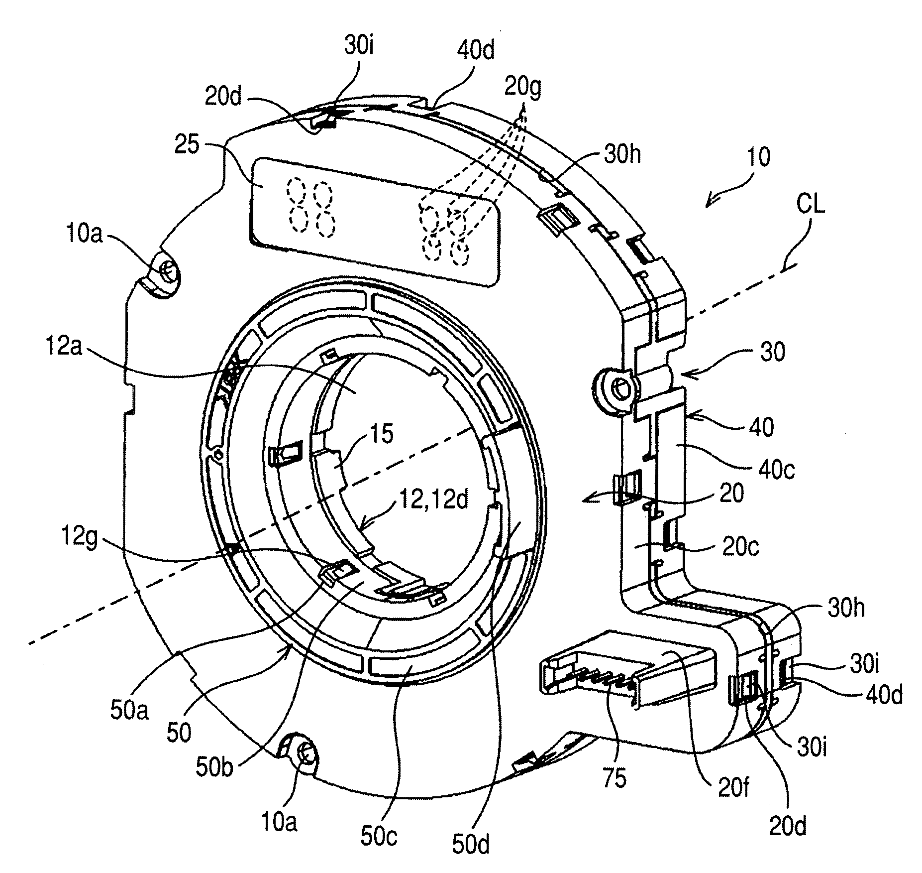
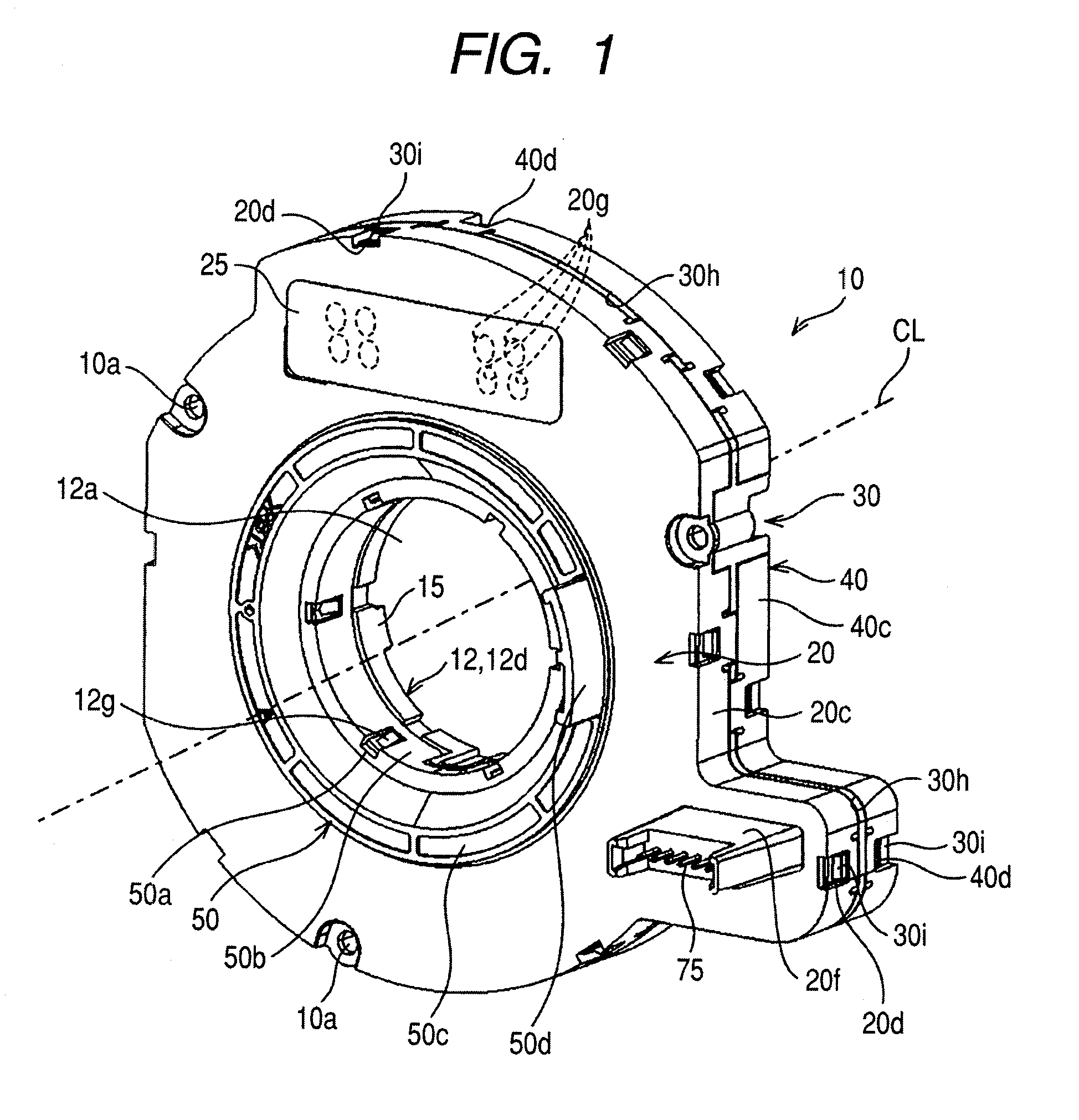
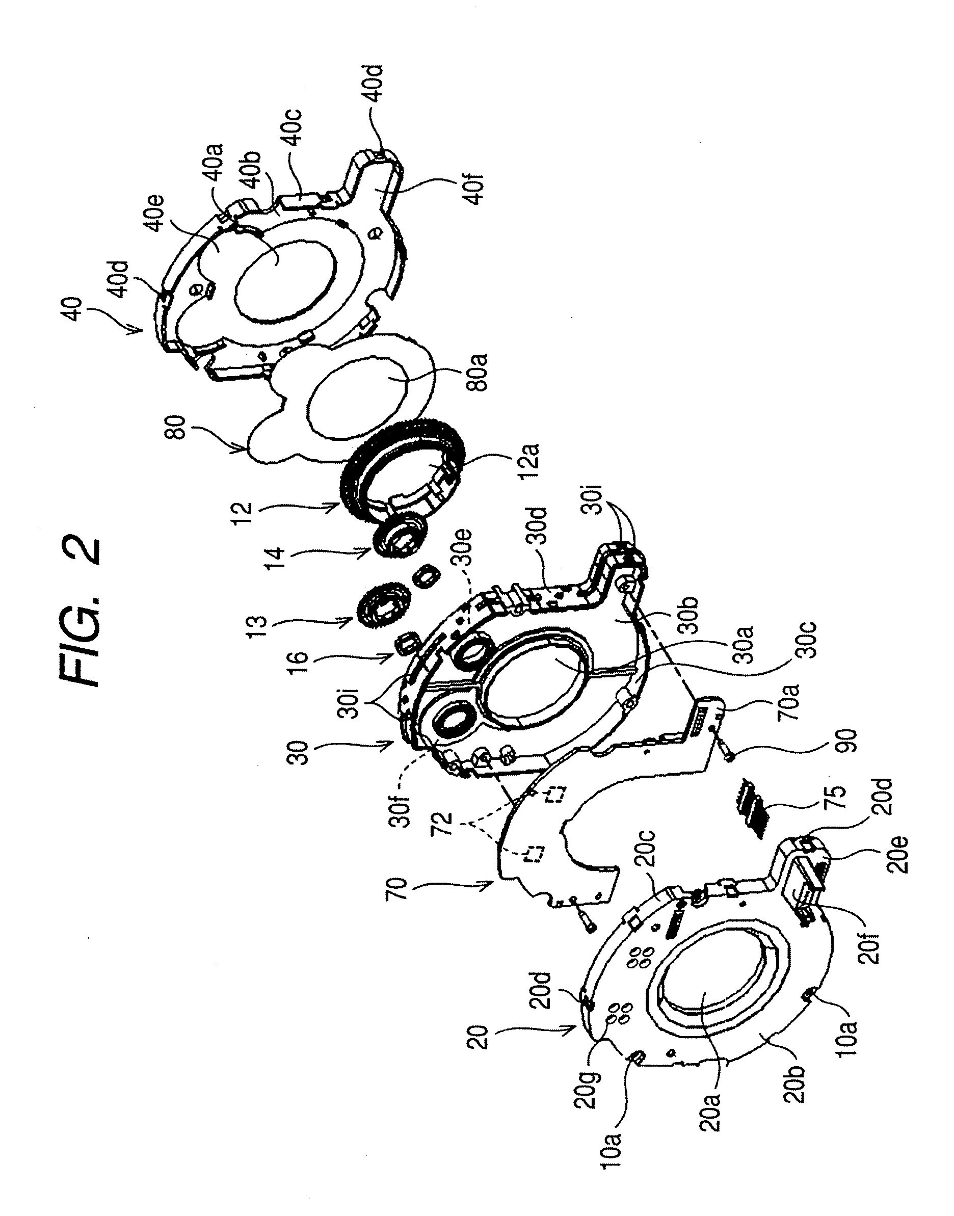
[0024]FIG. 1 is a perspective view showing a rotary angle detecting device 10 according to an embodiment. FIG. 2 is an entire exploded perspective view showing the rotary angle detecting device of FIG. 1. FIG. 3 is an exploded perspective view showing a relationship of a holder member, a main driving gear, and a driven gear in FIG. 2. FIG. 4 is a perspective view showing the meshing state between the main driving gear and the driven gear of FIG. 3. FIG. 5 is a front view showing the rotary angle detecting device of FIG. 1. FIG. 6 is a sectional view taken along the line VI-VI of FIG. 5. The rotary angle detecting device 10 is used to detect, for example, a rotary angle of a vehicle steering shaft which is a target to be detected.

[0025]The rotary angle detecting device 10 shown in FIG. 1 has a configuration in which a holder member (holder) 30, a first cover membe...


PUM


Abstract

A rotary angle detecting device is provided which includes: a main driving gear configured to rotate while being directly or indirectly connected to a detection target rotating about a predetermined axis; a driven gear configured to rotate while meshing with the main driving gear; a magnet provided at the center of the driven gear; a magnetic detection element configured to detect a variation in magnetic field in accordance with a rotation of the magnet; a circuit board having the magnetic detection element; and the circuit board is separated from the gears by a holder member.

Description

[0001]The present invention claims the benefit of Japanese Patent Application JP 2008-132395 filed in the Japanese Patent Office on May 20, 2008, the entire contents of which is incorporated herein by reference.”BACKGROUND[0002]1. Technical Field[0003]The present invention relates to a rotary angle detecting device suitable for detecting, for example, a rotary angle of a detection target such as a steering shaft of a vehicle.[0004]2. Related Art[0005]For example, in a posture control technology of a vehicle, a rotary angle detecting device is suitable for detecting a rotary angle of a steering shaft, rotating in accordance with an operator's steering operation, as an absolute angle. For the rotary angle detection, there is generally known a method in which a main driving gear rotates in accordance with a rotation of a steering shaft and an absolute angle is calculated on the basis of a phase difference of rotation occurring in plural driven gears meshing with the main driving gear. ...

Claims


Application Information

Patent Timeline
Patent Type & Authority Applications(United States)
IPC IPC(8): G01B7/30
CPCG01D11/245G01B7/30G01D5/12
Inventor SANO, TADASHI
Owner ALPS ALPINE CO LTD
Why Eureka
Try Eureka