
Radio frequency (RF) power amplifier and RF power amplifier apparatus

a power amplifier and radio frequency technology, applied in the direction of high frequency amplifiers, amplifiers with field-effect devices, gain control, etc., can solve the problem that the use of two discrete power amplifiers will no longer be allowed to achieve the further scale-down of the cellular phone terminal that supports multimode communication, and achieve the effect of reducing the adjacent channel leakage power ratio (acpr)

Active Publication Date: 2009-11-26
MURATA MFG CO LTD
View PDF2 Cites 34 Cited by
  • Summary
  • Abstract
  • Description
  • Claims
  • Application Information

AI Technical Summary

Benefits of technology

[0039]Advantageous effects obtained by a representative one of the inventions disclosed in the present application will be explained in brief as follows: According to the present invention, it is possible to cope with a load variation and an overload state in one RF power amplifier which is commonly used in general single type saturation-type nonlinear and non-saturation type linear amplifiers and which executes a first operation mode for saturation type nonlinear amplification and a second operation mode for non-saturation type linear amplification.
[0040]According to the present invention as well, it is possible to reduce an adjacent channel leakage power ratio (ACPR) in an overload state of a single type commonly-used RF power amplifier upon adaptation to a load variation in a second operation mode for non-saturation type linear amplification.

Problems solved by technology

However, the use of the two discrete power amplifiers will be no longer allowed to achieve the further scale-down of the cellular phone terminal that supports the multimode communications.

Method used


Image

  • Radio frequency (RF) power amplifier and RF power amplifier apparatus
  • Radio frequency (RF) power amplifier and RF power amplifier apparatus
  • Radio frequency (RF) power amplifier and RF power amplifier apparatus

Examples


embodiment

Description of Embodiment

[0131]Embodiments will next be descried in further detail.

>

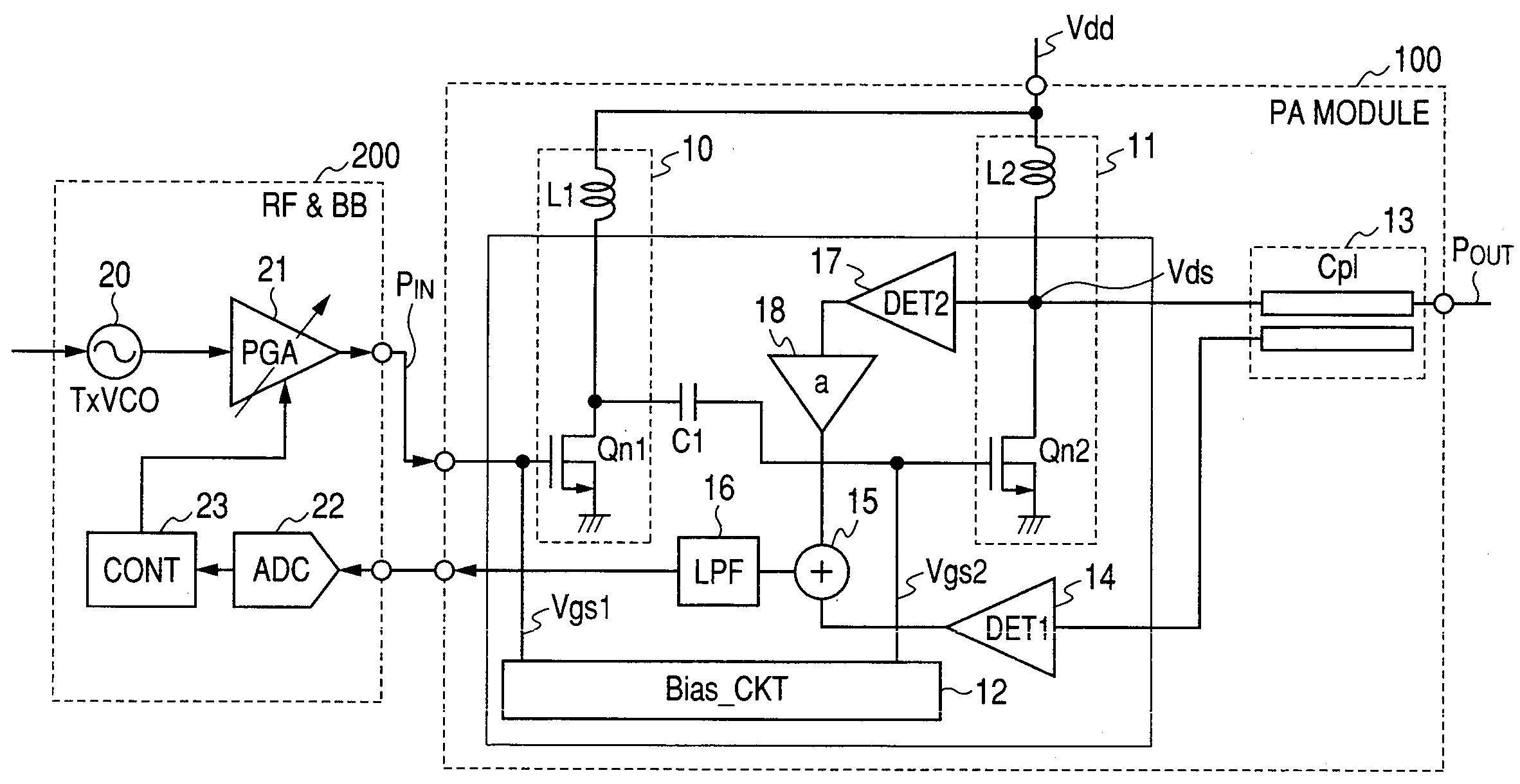
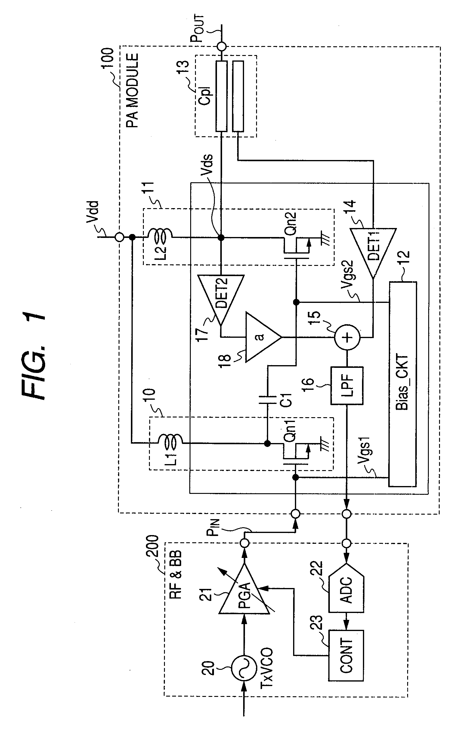
[0132]FIG. 1 is a diagram showing a configuration of a cellular phone terminal including an RF power amplifier 100 according to an embodiment of the present invention and a baseband digital signal processing / RF analog signal processing unit 200 which supplies an RF transmit signal to the RF power amplifier 100.

[0133]The cellular phone terminal shown in FIG. 1 performs GSM, EDGE and WCDMA communications with various base stations.

[0134]The baseband digital signal processing of the signal processing unit 200 generates a digital baseband transmit signal, which is converted to an analog baseband transmit signal by a D / A converter. The analog baseband transmit signal is frequency-upconverted to an RF transmit signal by an RF transmit signal processing unit including a transmit voltage control oscillator 20. The RF transmit signal from the transmit voltage control oscillator 20 is supplied to an RF transmi...


PUM


Abstract

An RF power amplifier has a final-stage amplifier stage which generates an RF transmit output signal, a signal detector which detects an RF transmit output level, a first detector, a second detector and a control circuit. The final-stage amplifier stage includes a transistor and a load element and performs saturation type nonlinear amplification and non-saturation type linear amplification. The first detector and the control circuit maintain the RF transmit output signal approximately constant with respect to a variation in load at an antenna at the saturation type nonlinear amplification. The second detector and the control circuit reduce an increase in the output voltage of the final stage transistor with respect to an overload state of the antenna at the non-saturation type linear amplification.

Description

CROSS-REFERENCE TO RELATED APPLICATIONS[0001]The disclosure of Japanese Patent Application No. 2008-131421 filed on May 20, 2008 including the specification, drawings and abstract is incorporated herein by reference in its entirety.BACKGROUND OF THE INVENTION[0002]The present invention relates to an RF power amplifier and an RF power amplifier apparatus for RF transmission, each of which is mounted in a communication terminal device like a cellular phone terminal that communicates with a base station, and particularly to a technique beneficial to realize two functions of a non-saturation type linear amplifier and a saturation type nonlinear amplifier by one RF power amplifier.[0003]The operation of a high-frequency power amplifier included in a cellular phone terminal is of a saturation operation in GSM of a basic mode in which only phase modulation is used. EDGE that also uses amplitude modulation along with the phase modulation is of a linear operation at an operating point where ...

Claims


Application Information

Patent Timeline
IPC IPC(8): H03F3/16
CPCH03F1/0261H03F3/19H03F2200/451H03F2200/393H03F3/245
Inventor TANAKA, SATOSHITANOUE, TOMONORI
Owner MURATA MFG CO LTD
Learn More