Method of operating an acoustic pulse echo ranging system

a ranger and echo ranging technology, applied in the field of acoustic pulse echo ranging system, can solve the problems of inability to detect, high frequency, ineffective detection,

a ranger and echo ranging technology, applied in the field of acoustic pulse echo ranging system, can solve the problems of inability to detect, high frequency, ineffective detection,

US20090290452A1Active Publication Date: 2009-11-26SIEMENS AG

Image

  • Method of operating an acoustic pulse echo ranging system
  • Method of operating an acoustic pulse echo ranging system
  • Method of operating an acoustic pulse echo ranging system

Examples


Embodiment Construction

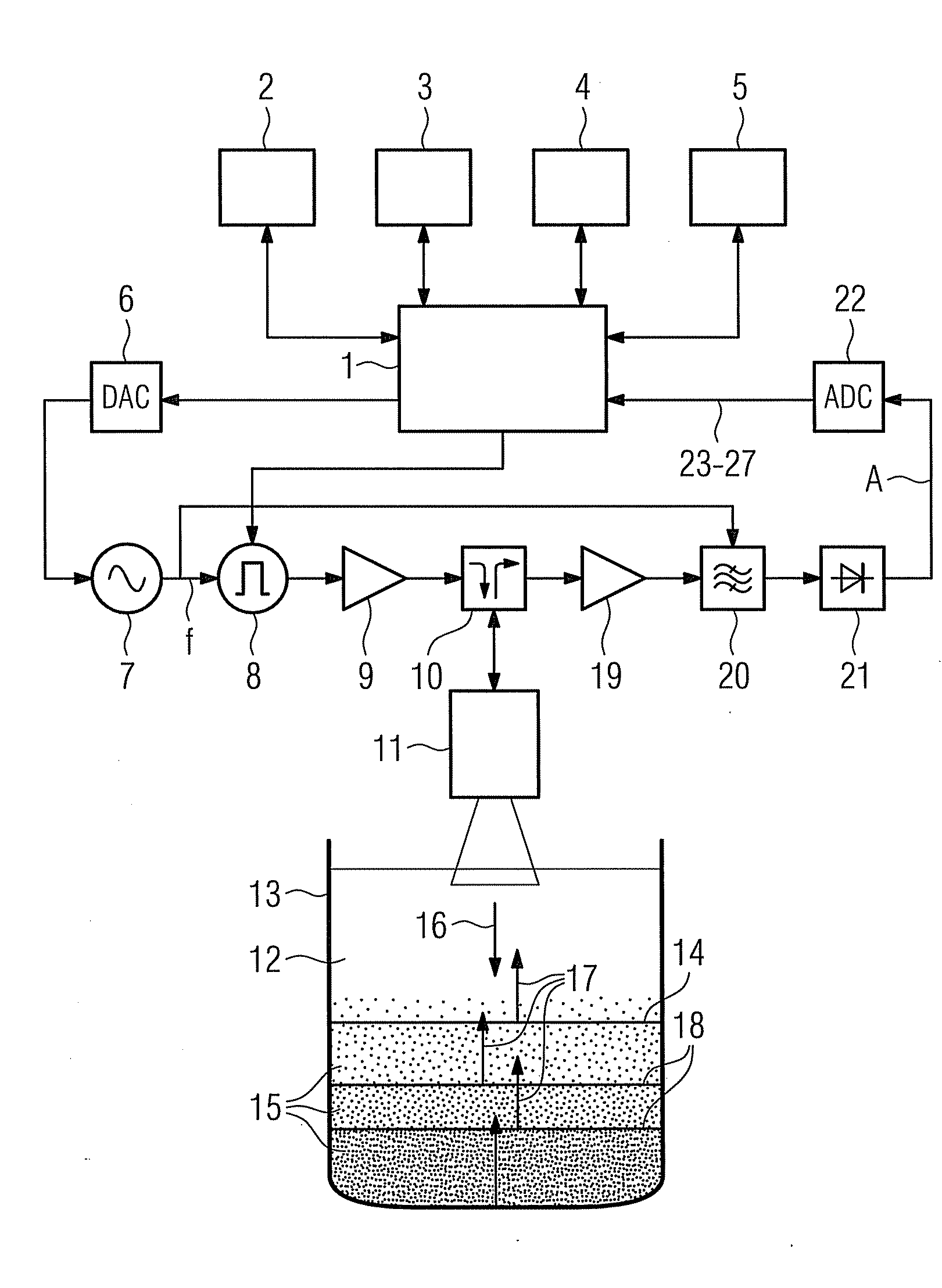
[0020]Referring to FIG. 1, there is shown a simplified schematic diagram of an acoustic pulse echo ranging system controlled by a microcontroller 1 which operates under a control program stored in read-only memory (ROM) 2, utilizing parameters stored in non-volatile random access memory (NOVRAM) 3, and provided with working memory in the form of random access memory (RAM) 4. An interface 5 provides for the export of measurement data and the import of operating parameters. Data may be exported in the form of a display, telemetry (e.g. bus) signals and / or alarm signals. The microcontroller 1 also controls, via a digital to analog converter 6, a voltage controlled oscillator 7 to successively increase or decrease its output frequency f over a range from e.g. 60 to 800 kHz. A pulse generator 8 is triggered by the microcontroller 1 to generate bursts of the instantaneous frequency f and to apply these bursts via a power amplifier 9 and a multiplexing gate or switch 10 to a wideband acous...


PUM


Abstract

A method of operating an acoustic pulse echo ranging system is provided. A series of acoustic energy pulses of successively increasing or decreasing burst frequencies are transmitted through a transducer assembly. For each transmitted energy pulse associated echoes are received and converted into an echo function over time. The obtained echo function is stored in a two-dimensional pattern whose first dimension is the burst frequency and whose second dimension is the time. Based upon the two-dimensional pattern a frequency response function is evaluated as a function of echo function values over burst frequency at a selected point of time.

Description

CROSS REFERENCE TO RELATED APPLICATIONS[0001]This application claims priority of European Patent Application No. 08009205.9 EP filed May 19, 2008, which is incorporated by reference herein in its entirety.FIELD OF INVENTION[0002]The invention relates to a method of operating an acoustic pulse echo ranging system.BACKGROUND OF INVENTION[0003]In a number of applications, it is necessary to monitor liquids containing significant quantities of suspended materials, which materials may tend to separate or accumulate as a separate phase beneath a body of clearer liquid. Suspended material in liquids tends to absorb, reflect and disperse acoustic energy, although the extent of this effect is frequency dependent. For example, in potable water clarifiers a high frequency is required to detect very small particles in the clear phase. Such high frequency, however, does not work effectively to detect e.g. the density and level of sludge in sewerage treatment plants which, in addition, have sever...

Claims


Application Information

Patent Timeline
26 Nov 2009
Publication
US20090290452A1
IPC
G01F23/296
CPC
G01F23/2962; Y10S367/908; G01S15/88; G01S15/104
Inventors
LYON, GEORGE QUINTON